


EX200 Electro-Hydraulic Actuator Positioner
Bifold Orange Limited.
Drwg. No.: ORM0001 Issue : 1 Date : 24/06/2015 Page :
4 of 20
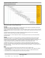
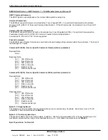
EX200 Part Number Selection Chart
Other options available on request to Bifold Orange.
Operation
The instrument compares two analogue signals, one representing the desired position (command signal) and the other
representing the actual position (feedback signal) of the actuator.
A difference between these two signals will cause one of the EX200 outputs to operate, driving the actuator to the desired
position. A positional Dead-
zone may be adjusted to overcome “hunting” problems associated with mechanical overrun of
the actuator.
The speed of transit of the actuator can be reduced by selecting the stepping mode that provides independently
adjustable on and off times for the open and close solenoid operation.
An OK light is present on the front display that is linked to the Auxiliary Solenoid Output, this is lit when the EX200 is
operating correctly.
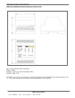
Physical
The
EX200 with part number “D” for housing selection is contained in a small DIN rail mounted polyester enclosure
measuring 85 x 70 x 58h. The circuit boards are coated with a resist layer that protects the track from moderate
condensation and mould growth problems. Connections are via screw terminals with a capacity of 2.5mm
2
but the use of
ferrules or crimps is recommended. All adjustments are accessible on the front panel of the enclosure. Initial
configuration adjustments are via internal jumper links, usually set to customer requirements on order.
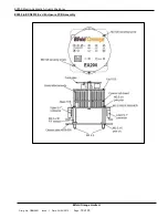
The EX200
with part number “C” for housing selection is mounted on a chassis plate and housed within an Ex d
enclosure. The circuit boards are coated with a resist layer that protects the track from moderate condensation and
mould growth problems. Connections within the Ex d enclosure
are by factory assembled 0.1” connectors and must not
be disturbed or re-wired.
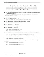
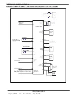
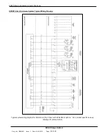
Wiring
Wiring should be completed by suitably trained personnel taking into account the following notes:
To ensure RFI compliance the analogue signals should be routed in copper braided screened cables with a fill factor
density of at least 0.7.
The screens should be terminated to the metal of the actuator housing, ideally at a suitable metal cable gland.
Signal cables should be routed separately from power and switching conductors.


