Installation, Operation and Maintenance Manual
September 2019
MAN720_IMVS2000v2_IOM Rev. 6
Section 6: Configuration Parameters
Configuration Parameters
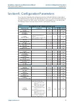
PARAMETERS OF THE “VIEW/SETUP MODE” MENU
PARAMETER NAME
DESCRIPTION
RANGE
DEFAULT
VALUE
R/W
(1)
AVAILABLE
ON (2) (3)
Sign. En.
(Signatures Enabled)
If it is set as “Yes” it is possible to perform com-
mands “Baseline Signature” and “Maintenance
Signature” otherwise they do not work.
Yes, No
Yes
R/W
Local, Serial,
Bus
Op. Pos. %
(Open Position Hyster-
esis)
It defines the tolerance for considering the actua-
tor/valve as open (it can be “masked” by the Closed
Position Hysteresis).
Its value affects the “OPEN” Digital Output (see
DOs for details) and the activation of the OPOS
alarm (see Section 8 for details).
It affects the validity of the PST (PSSR Alarm) and
FST starting points and if set to a value different to
default one it could influence the PST and
FST results.
0 – 90.0 %
3%
R/W
Local, Serial,
Bus
Cl. Pos. %
(Closed Position Hys-
teresis)
It defines the tolerance for considering the actua-
tor/valve as closed. Its value affects the “CLOSED”
Digital Output (see Section 5.2.3 for details) and
the activation of the CPOS alarm
(see Section 8 for details).
It affects the validity of the PST (PSSR Alarm) and
FST starting points and if set to a value different
to default one it could influence the PST and FST
results.
0 – 90.0 %
3%
R/W
Local, Serial,
Bus
Op. Time %
(Opening Time Hys-
teresis
It defines the tolerance for the generation of the
following alarms: SOBT, FOBT, SOTT and FOTT.
See Section 8 for details.
This parameter affects the “duration” of the Open-
ing FST time window. It is suggested to perform
a new “Baseline Signature” after changing this
parameter to better compare the next Signatures
and FSTs.
0 -200%
20 %
R/W
Local, Serial,
Bus
Cl. Time %
(Closing Time Hyster-
esis)
It defines the tolerance for the generation of the
following alarms: SCBT, FCBT, SCTT and FCTT.
See Section 8 for details.
This parameter affects the “duration” of the Closing
FST time window. It is suggested to perform a new
“Baseline Signature” after changing this parameter
to better compare the next Signatures and FSTs.
0 -200 %
20 %
R/W
Local, Serial,
Bus
FST. Pr. %
(FST Pressure Hyster-
esis)
It defines the tolerance for the generation of the
following alarms: OHBP, OLBP, CHBP and CLBP.
See Section 8 for details.
0 -100 %
20 %
R/W
Local, Serial,
Bus
H. Pr. Lim.
(High Pressure Limit)
It is applicable only if “Act. Mode” ≠ “Double”.
It defines the threshold for the generation HSP
alarm. See Section 8 for details.
The pressure measurement unit (bar or psi) is deter-
mined by the setting of the “Pres. M.U.” parameter.
0 – 400 bar
(0 – 5800 psi)
400 bar
(5800 psi) R/W
Local, Serial,
Bus
L. Pr. Lim.
(Low Pressure Limit)
It is applicable only if “Act. Mode” ≠ “Double”.
It defines the threshold for the generation LSP
alarm.
See Section 8 for details.
The pressure measurement unit (bar or psi) is deter-
mined by the setting of the “Pres. M.U.” parameter.
0 – 400 bar
(0 – 5800 psi)
0 bar
(0 psi)
R/W
Local, Serial,
Bus
H. Proc. L.
(High Process Pressure
Limit)
It is applicable only if the Process Pressure Sensor
is present (“Proc. S” is not set to “None”). It defines
the threshold for the generation HPP alarm.
See Section 8 for details.
The pressure measurement unit (bar or psi) is deter-
mined by the setting of the “Pres. M.U.” parameter.
0 – 400 bar
(0 – 5800 psi)
400 bar
(5800 psi) R/W
Local, Serial,
Bus
41
Summary of Contents for IMVS2000v2
Page 2: ......


