


September 2019
Installation, Operation and Maintenance Manual
MAN720_IMVS2000v2_IOM Rev. 6
MAN720_IMVS2000v2_IOM Rev. 6
Section 10: Installation – Start-Up
Installation – Start-Up
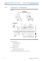
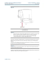
Figure 39
4.
Using a 6 mm Allen key, loosen the four screws fixing the cover and remove it. At the end of
wiring connections replace the cover and fix the 4 screws with a tightening torque from 15 to 20 Nm.
10.6.3
Unused entries
WARNING
Replace the plastic plugs, install present at the unused entries certified explosion-proof
plugs and block with a thread sealant to guarantee the tightening. Not performing the
above recommendation will invalidate the safety protection in case of presence of
hazardous atmospheres.
10.6.4
Cables requirements – EMC protection
The table below summarizes the specifications of the cables, for connecting with the IMVS2000v2.
Particularly, it indicates if a cable needs to be armoured or shielded.
“Shielded” must be considered as a stricter condition than “Armoured."
”It is possible to use a shielded cable instead of a required armoured cable, but it is not possible to use
an armoured cable instead of a required shielded cable.
Table 13.
CONNECTION TYPE
CABLES REQUIREMENT (Armoured or Shielded)
Main Supply
None
SISA – SISB
Max Length 3 mt.
SOV A – SOV B
None
Digital Input
None
Digital Output
None
MODBUS
Shielded (see [3] for details).
HART – 4-20mA Analogue Output
Shielded. Maximum Load (cable + termination resistance) = 300 ohm.
See [2] for details
96
Summary of Contents for IMVS2000v2
Page 2: ......