- 43 -
INST
A
ll
ATI
o
N
INSTAllATIoN
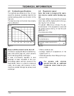
Fig. 6.13
K
l
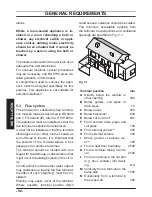
• Remove the side panels or move the low-
er part of the side panels as indicated in
Fig. 6.14 and pull the control panel. When
completely pulled out, the panel can rotate
45° downwards to facilitate the operations
on the internal parts.
Fig. 6.14
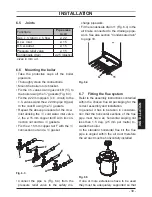
• Loosen the screws M and remove the ser-
vice panel (Fig. 6.15).
Fig. 6.15
M
For the electrical connection to the boiler
use electric wire switch conform to the cur-
rent regulations, with flexible cord, each
core having a cross section area
not less
than 0,75 mm
2
.
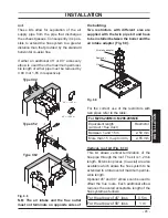
• Connect the electrical supply flexible
cord coming from the fused spur isolation
switch to the power supply terminal block
of the boiler (Fig. 6.16) keeping the same
connections for the live (brown wire) and
the neutral (blue wire). External 3 A fuse or
fused plug with same current rating is rec-
ommended.
Do not connect live wires to
terminals to which the room thermostat
must be connected.
• Connect the earth wire (yellow/green).
Connection of a room thermostat
The room thermostat must be connected to
the terminal block situated next to the con-
trol panel.
When connecting any type of external
control, the link N in Fig. 6.16 must be
removed.
Summary of Contents for Riva Plus HE M296.24SC
Page 56: ...56 NOTES...
Page 57: ...57 NOTES...


