background image

- 40 -

INST

A

ll

ATI

o

N

INSTAllATIoN

there is no sag in the flue pipe and a mini-
mum fall of 1,5 deg. (25 mm per metre) over 
the  whole  length  towards  the  boiler  is  en-
sured.
Before  fitting  the  flue  system,  ensure  that 
the flue gasket shown in Fig. 6.5 (given with 
the boiler) is fitted to the boiler.

6.8  Choice of flue

The following flue kits are available for con-
necting to the boiler:

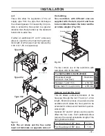
Standard horizontal flue kit (Fig. 6.6 A)

Fig. 6.6

B

A

C

45°

90°

Type C

13

Co-axial 60/100 mm - nominal length 1 m
This  kit  is  normally  supplied  with  the  boil-
er  and  can  be  fitted  to  allow  discharge  to 
the rear or either side of the boiler via the 
flanged  boiler  adapter  elbow.  Minimum 
length required is 0.3 m. Maximum equiva-
lent length of 2,7 metres (for M296.24SM/C 
and M296.28SM/C) can be achieved utilis-
ing  extensions.  This  flue  system  can  only 
be used to discharge horizontally, it is not 
designed to enable termination in the verti-
cal plane.

Vertical kit with 90° elbow (Fig. 6.6 b)

Co-axial 60/100 mm.
Supplied  with  a  straight  flanged  adapter 
a  co-axial  elbow  and  a  co-axial  pipe  with 
terminal, this kit allows for a vertical rise of 
0,5  m  from  the  boiler.  In  all  circumstances 
the  flue  terminal  must  discharge  horizon-
tally and the equivalent flue length must not 
exceed  2,7  metres  (for  M296.24SM/C  and 
M296.28SM/C).

Elbows 45° & 90° (Fig. 6.6 C)

Coaxial 60/100 mm.
Elbow kits enable the standard flue kits to be 
offset to overcome obstructions or ensure 
the correct clearances for the flue terminal. 
Each elbow used in addition to the standard 
flanged  elbow  reduces  the  overall  accept-
able length of the flue system as follows:

For the elbow of 45° loss

0,5 m

For the elbow of 90° loss

1 m

Twin pipe kits ø 80 mm (Fig. 6.7 - Fig. 6.8)

Fig. 6.7

Type C

12

Various  twin  (split)  pipes  kits  and  optional 
accessories (elbows) are available to assist 
in the termination of the flue where the boiler 
is installed in a location remote to an outside 

Summary of Contents for Riva Plus HE M296.24SC

Page 1: ...Wall hung fanflue roomsealed high efficiency gas boiler User manual and Installation instructions Riva Plus HE Models G C Appl No M296 24SM C 47 583 24 Combi boiler M296 28SM C 47 583 25 Combi boiler...

Page 2: ...ter systems in the UK and to encourage regular servicing to optimise safety efficiency and performance Benchmark is managed and promoted by the Heating and Hot water Industry Council For more informat...

Page 3: ...otified to Local Area Building Control either directly or through a Competent Persons Scheme A Building Regulations Compliance Certificate will then be issued to the customer who should on receipt wri...

Page 4: ...ply system com patible with its performance and output can be used only for those purposes for which it has been specially designed must not be touched by children or by those unfamiliar with its oper...

Page 5: ...eyes and throat Vapour is harmful Inflammable do not extinguish with water Precautions Do not incinerate Avoid contact with broken leaking phials Do not purposely puncture First aid medical attention...

Page 6: ...uent problem this method if you have a subsequent problem following the addition of an exter nal control you can eliminate the boiler from your fault analysis If the boiler is fitted with a digital pr...

Page 7: ...5 Initial filling of the system 45 7 6 Condensate pipe and traps 46 7 7 Lighting the boiler 47 7 8 Checking the gas pressure at the burner 47 7 9 Checking the burner ignition 48 7 10 Checking the igni...

Page 8: ...pressure gauge 5 Time switch c h control 6 Lock out signal lamp 7 Lockout reset button 8 Function selector and c h temp control knob 9 D h w temperature control knob 10 Appliance operation lights 1 3...

Page 9: ...ination observed is not included in the above table a fault may be indicated Reference should be made to the following table In this case switch off the boiler as de scribed in section Extinguishing t...

Page 10: ...h w supply checking that the pressure indicated on pressure gauge 4 is not lower than that shown in Fig 2 2 If the pressure reading on the pressure gauge is below that shown in Fig 2 2 then the syste...

Page 11: ...isolation switch The appliance operation light 10 Fig 2 4 will flash every 4 seconds stand by condition If the boiler is to be used for c h and d h w position the function selector 8 as in Fig 2 4 The...

Page 12: ...55 C Fig 2 8 by turning the temperature control knob 9 Fig 2 8 Minimum Maximum Adjustment of the d h w temperature is com pletely separate from that of the c h circuit The adjustment system integrate...

Page 13: ...or 8 to the position shown in Fig 2 10 The appliance operation light 10 will flash every 4 seconds Fig 2 10 10 8 When you do not expect to use the boiler for a long period Switch off the electricity s...

Page 14: ...e programming the OFF time Set the OFF time as explained above for the ON setting and confirm by pressing the en ter button C Proceed in the same way for other settings Setting example shown in Fig 2...

Page 15: ...A in the TIMER position Set the time delay by pressing the button D or E and the operation can be forced on or off by pressing the button F The time delay can be set within the follow ing ranges 1 to...

Page 16: ...g and to continue programming the OFF time Set the OFF time as explained above for the ON setting and confirm by pressing the OK button C Proceed in the same way for other settings Setting example sho...

Page 17: ...edly the button A until the dis play shows the symbol TIMER Set the time delay by pressing the button D or E and the operation can be forced on or off by pressing the button F The time delay can be se...

Page 18: ...run is accessible an attempt may be made to free the obstruction by pouring hot water over the exposed pipe an cleaning any blockage from the end of the pipe If this fails to remedy the problem the a...

Page 19: ...ation You should check that the pressure on the temperature and pressure gauge Fig 2 2 on page 10 is not below the correct setting If required top up the system correctly as described in the section R...

Page 20: ...n Au thorised Service Centre Engineer If the left appliance operation light 10 Fig 3 3 flashes very quickly the boiler is detecting a fault Fig 3 3 10 8 In this case or in case of prob lems other than...

Page 21: ...21 INSTALLATION TECHNICAL INFORMATION 4 TECHNICAL INFORMATION 4 1 Overview Fig 4 1 20 22 42 38 39 31 26 40 30 28 19 23 37 29 27 25 41 21 17 36 18 24 35 43 44...

Page 22: ...D h w outlet pipe 16 C h flow valve 17 Fan 18 Air pressure sensor test points 19 Air pressure sensor 20 Flue temperature probe NTC 21 Condensing heat exchanger 22 Safety thermostat 23 C h temperature...

Page 23: ...Gas valve inlet pressure test point 35 D h w temperature probe NTC 36 Three way diverter valve 37 D h w heat exchanger 38 Primary circuit pressure switch 39 Combustion chamber over heat 40 Flame detec...

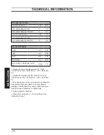
Page 24: ...inimum return temperature C 40 Maximum pressure kPa 250 bar 2 5 Minimum pressure kPa 30 bar 0 3 Available head in 1000 l h kPa 25 bar 0 25 Seasonal effiency G20 88 0 Seasonal effiency G30 G31 C 89 0 t...

Page 25: ...Gas rate minimum ch dhw Natural G20 m3 h 0 79 Butane G30 kg h 0 59 Propane G31 kg h 0 58 Gas restrictors references N mm 100 Natural G20 12 120 Butane G30 12 77 Propane G31 12 77 Electrical data Volt...

Page 26: ...volume in the boiler up to 1 bar l kg 1 4 A referred to the net calorific value at 15 C and 1013 25 mbar G20 34 02 MJ m3 G31 46 34 MJ kg B referred to the gross calorific value at 15 C and 1013 25 mba...

Page 27: ...Minimum return temperature C 40 Maximum pressure kPa 250 bar 2 5 Minimum pressure kPa 30 bar 0 3 Available head in 1000 l h kPa 25 bar 0 25 Seasonal effiency G20 88 0 Seasonal effiency G30 G31 C 89 0...

Page 28: ...Gas rate minimum ch dhw Natural G20 m3 h 0 92 Butane G30 kg h 0 69 Propane G31 kg h 0 68 Gas restrictors references N mm 100 Natural G20 14 120 Butane G30 14 77 Propane G31 14 77 Electrical data Volt...

Page 29: ...olume in the boiler up to 1 bar l kg 1 5 A referred to the net calorific value at 15 C and 1013 25 mbar G20 34 02 MJ m3 G31 46 34 MJ kg B referred to the gross calorific value at 15 C and 1013 25 mbar...

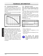
Page 30: ...ure of the thermostatic valves or system component cocks the by pass valve ensures a mini mum flow of water through the primary heat exchanger 4 6 Expansion vessel Note this boiler is designed for ope...

Page 31: ...s necessary to com plete a Declaration of Conformity to indicate compliance to I S 813 2002 This appliance must be installed by a competent person in accordance with the Gas Safety installation Use Re...

Page 32: ...t the position of the terminal allows a free passage of air across at all times The terminal should be located with due regard for the damage or discoloration that might occur to building products in...

Page 33: ...e complete instal lation should be tested for tightness For Ireland IE refer to I S 813 2002 5 5 Air supply The room in which the boiler is installed does not require a purpose provided air vent 5 6 V...

Page 34: ...he following notes are given for general guidance For Ireland IE refer to I S 813 2002 Pipework The return temperature must not be lower of 40 C Copper tubing to BSEN 1057 is rec ommended for water pi...

Page 35: ...tic water pressure of 10 bar Where it is likely that the mains domestic water pressure may exceed 5 bar it is possible due to internal water hammer effects that the pressure within the domestic system...

Page 36: ...of the local water company 5 11 Electrical supply Warning this appliance must be earthed External wiring to the appliance must be carried out by a competent person and be in accordance with the curre...

Page 37: ...hich permits a complete switching off in the conditions of the overvoltage category III Refer to section Electrical connections to page 42 in this chapter for the electrical con nections In no circums...

Page 38: ...ecautions Before mounting the bracket check that the dimensions for fitting the exhaust fume duct are complied with refer to the leaflet includ ed with the flue kit packed separately Utilise the paper...

Page 39: ...mm copper tail F with the connection nut and a gasket Fig 6 3 A A B C C D J E F Connect the pipe G Fig 6 4 from the pressure relief valve to the safety dis charge pipework Fit the condensate drain 11...

Page 40: ...ontally it is not designed to enable termination in the verti cal plane Vertical kit with 90 elbow Fig 6 6 B Co axial 60 100 mm Supplied with a straight flanged adapter a co axial elbow and a co axial...

Page 41: ...d with the twin pipe kit and have to be installed between the boiler and the air intake adapter Fig 6 9 Fig 6 9 Air intake adapter Restrictor Gasket For the correct use of the restrictors with twin pi...

Page 42: ...d elbows can be added to ex tend the kit s length The chart of Fig 6 12 gives the allowable dimensions of the ducts a and b of Fig 6 11 Fig 6 12 a vertical length m 0 0 0 2 0 4 0 6 0 8 1 0 1 2 1 4 1 6...

Page 43: ...e having a cross section area not less than 0 75 mm2 Connect the electrical supply flexible cord coming from the fused spur isolation switch to the power supply terminal block of the boiler Fig 6 16 k...

Page 44: ...flexible cord and the external control flexible cord as illustrated in Fig 6 18 Lock the flex ible cords in place with the flexible cord clamps Fig 6 18 To the fused spur isolation switch To the exter...

Page 45: ...rical safety shall be carried out by a competent person i e polarity earth con tinuity resistance to earth and short circuit If a fault has occurred on the appliance the fault finding procedure should...

Page 46: ...n on the c h sys tem and run it until the temperature has reached the boiler operating tempera ture The system must then be immedi ately flushed through This procedure must be repeated twice more Duri...

Page 47: ...ence control p c b will go to lockout and the lock out sig nal lamp 6 will appear To reset the boiler press and release the boiler reset button 7 7 8 Checking the gas pressure at the burner This boile...

Page 48: ...and disconnect the pressure gauge Reassemble the sealed chamber lid and the front panel of the case see Disman tling the external panels to page 53 If the maximum and minimum gas pres sures measured...

Page 49: ...ignition attempts within about three minutes the lock out signal lamp 6on page 8 must appear To reset the boiler press and release the boiler reset button 7on page 8 7 11 Checking the flue system The...

Page 50: ...appliance be inoperative when freezing conditions may occur Fill in the details required on the Boiler Guarantee Certificate and hand to the User advising them to return the correct section for boile...

Page 51: ...ve the burner 41on page 23 See section Ignition and detec tion electrodes in the service manual for detailed instructions Carry out the conversion for the type of gas replacing the burner injectors co...

Page 52: ...5 seconds until the lamps 10 briefly blinks simultaneously Open the gas cock 14 in Fig 8 7 To reset the boiler to the normal operation turn it ON by the function selector 8 on the desired operation a...

Page 53: ...nce and turn off the gas cock before carrying out any procedures whatsoever for cleaning maintenance opening or dismantling boiler panels 9 2 Dismantling the external panels Front panel Loosen the thr...

Page 54: ...not less than 1 bar See also section Expansion vessel to page 30 If the pressure is lower take steps to correct the pressure level 9 8 Cleaning the burner The sloping and multi gas type burner 41on pa...

Page 55: ...perational pressures and adjust as neces sary as described in section Checking the gas pressure at the burner to page 47 9 13 Water inhibitor concentration Where chemical products are used the level o...

Page 56: ...56 NOTES...

Page 57: ...57 NOTES...

Page 58: ...ect the customer s statutory rights If yes and if required by the manufacturer has a water scale reducer been fitted Condensing Boilers only The condensate drain has been installed in accordance with...

Page 59: ...er Name Company Name Telephone No Gas Safe Register No Comments Signature Date Engineer Name Company Name Telephone No Gas Safe Register No Comments Signature Date Engineer Name Company Name Telephone...

Page 60: ...1796215484 17962 1548 4 0312 60A5 UK Biasi UK Ltd Commercial Road Leamore Enterprise Park WALSALL WS2 7NQ Sales Tel 01922 714600 Tech Service Tel 01922 714636 www biasi co uk 16 01 2012 N...

Reviews: