- 35 -
INST
A
ll
ATI
o
N
- 35 -
INST
A
ll
ATI
o
N
GENERAl REQUIREMENTS
The by-pass is calibrated to assure a mini-
mum flow of 200-300 lts/hr through the main
heat exchanger.
If you are installing a system that includes
thermostatic radiator valves (TRV) and/or
small bore (8-10 mm) it may be necessary
to fit an external by-pass to facilitate correct
operation of the boiler.
The fitting of an external bypass helps to
prevent and limit system noise.
Air release points
These must be fitted a tall high points where
air will natural collect and must be sited to
facilitate complete filling of the system.
Expansion vessel
The appliance has an integral sealed ex-
pansion vessel to accommodate the in-
crease of water volume when the system is
heated. Refer to Fig. 4.4 on page 30 for its
technical data.
If the heating circuit has an unusually high
water content, calculate the total expansion
and add an additional sealed expansion
vessel with adequate capacity.
Mains water feed: central heating
There must be no direct connection to the
mains water supply even through a non re-
turn valve, without the approval of the Local
Water Authority.
Mains water feed: hot water supply
The domestic section of the boiler is de-
signed to withstand an internal domestic
water pressure of 10 bar. Where it is likely
that the mains domestic water pressure may
exceed 5 bar, it is possible due to internal
“water hammer” effects that the pressure
within the domestic system can increase to
a level in excess of the 10 bar limit.
In these circumstances it is therefore rec-
ommended that a 3 bar pressure reducing
valve be fitted to the incoming mains wa-
ter supply and a mini expansion vessel in-
stalled on the domestic circuit.
These devices will protect the boiler and the
domestic system from damage due to ex-
cessive domestic water pressure.
Filling
A method for initially filling the system and
replacing water lost during servicing must
be provided and it must comply with local
water authority regulations.
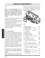
The correct method is shown in Fig. 5.4.
The temporary connection must be re-
moved immediately after filling.
Fig. 5.4
Temporary
connection
Control valve
Control valve
Double check valve
Supply pipe
(cold water inlet)
C.h. return pipe
The installer should ensure that no leaks ex-
ist either inside the boiler or on the system
as frequent filling of the system could cause
premature scaling of the heat exchanger.
5.9 Domestic water
The domestic water installation must be in
accordance with the relevant recommenda-
tions of BS 5546. Copper tubing to BS EN
1057 is recommended for water carrying
pipework and must be use for pipework car-
rying potable water.
For Ireland (IE), refer to I.S.813.2002.
Summary of Contents for Riva Plus HE M296.24SC
Page 56: ...56 NOTES...
Page 57: ...57 NOTES...


