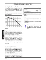
- 35 -
INST
ALLA
TION
INSTALLATION
Fig. 6.8
Type C52
90°=---1,65 m
45°=---0,90 m
Type C42
Type C82
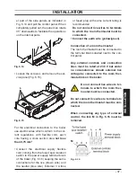
Two restrictors with different size are
supplied with the twin pipe kit and have
to be installed between the boiler and
the air intake adapter (Fig. 6.9).
For the correct use of the restrictors
with
twin pipes
refer to the table:
Equivalent length
(air duct + flue duct)
Restrictor
Between 1 and 15 m
ø 50 mm
More than 15 m up to 30 m
ø 55 mm
Fig. 6.9
Air intake adapter
Restrictor
Gasket
Vertical- roof kit (Fig. 6.10)
This kit allows vertical termination of the
flue pipe through the roof. The kit is 1.2 m
in length. Extension pieces (Co-axial) are
also available which allows the flue system
to be extended to a total overall maximum
permissible length.
Optional 45° and 90° elbows can be used to
offset the flue route. Each additional elbow
reduces the overall acceptable length of the
flue system as follows:
For the elbow of 45° loss
0,5 m
For the elbow of 90° loss
1 m
Fig. 6.10
90°=---1 m
45°=---0,5 m
max =8,5 m
ø 125
Type C32
Summary of Contents for RIVA PLUS HE 24S ERP
Page 55: ......


