- 33 -
INST
ALLA
TION
INSTALLATION
•
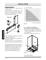
Fix the c.h. valves
A
and gas cock
B
(¾”)
to the boiler using the ¾” gaskets (Fig. 6.3)
•
Fix the ø 22 mm pipes
C
(c.h. circuit) to the
c.h. valves A
and the ø 22 mm pipe
D
(gas)
to the cock
B
using the ¾” gaskets.
Fig. 6.3
A
A
B
C
C
D
•
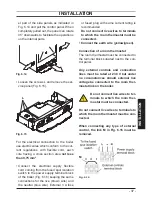
Connect the pipe E (Fig. 6.4) from the
pressure relief valve to the safety dis
-
charge pipework.
•
Fit the condensate drain 10 (Fig. 6.4) in
the air brake connected to the drainage
pipework. See also
section "Condensate
drain
" to page 27
.
Fig. 6.4
E
10
6.7
Fitting the flue system
Refer to the assembly instructions con
-
tained within the chosen flue kit packaging
for the correct assembly and installation.
In general, it has to be taken in considera
-
tion that the horizontal sections of the flue
pipe must have an horizontal sloping not
less than 1.5 deg. (25 mm per metre) to
-
wards the boiler.
In the standard horizontal flue kit (Fig. 6.6
A) the flue pipe is angled within the air duct
therefore the air duct must be horizontally
installed.
If one or more extensions have to be used
they must be adequately supported so that
there is no sag in the flue pipe and a mini
-
mum fall of 1,5 deg. (25 mm per metre) over
the whole length towards the boiler is en
-
sured.
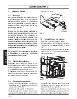
Before fitting the flue system, ensure that
the flue gasket shown in Fig. 6.5 (given with
the boiler) is fitted to the boiler.
Fig. 6.5
6.8
Choice of flue
The following flue kits are available for con
-
necting to the boiler:
Standard horizontal flue kit (
Fig. 6.6 A)
Co-axial 60/100 mm - nominal length 1 m
This kit can be fitted to allow discharge to
the rear or either side of the boiler via the
flanged boiler adapter elbow. Minimum
length required is 0.3 m. Maximum equiva
-
lent length of 2,7 metres can be achieved
utilising extensions. This flue system can
only be used to discharge horizontally, it is
not designed to enable termination in the
Summary of Contents for RIVA PLUS HE 24S ERP
Page 55: ......


