background image

- 74 -

MAINTENANCE

MAINTENANCE

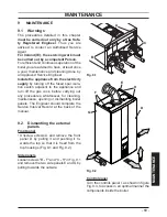
Fig. 9.16

Model Advance Plus 30S ERP

Nominal heat input 

(A) (E)

kW

30,0

Nominal efficency

%

98,2

Combustion efficency

%

98,3

Air index

n

1,2

Flue gas CO

2

 content

%

9,2 - 9,8

Flue gas O

2

 content

%

3,9

Flue gas CO

 content

ppm

160

Flue gas temperature

°C

81,6

Values refer to tests with a an 80 mm double exhaust 

split by 1 + 1 m and natural gas G20 and a supply / 

return heating temperature of 60°/80°C.

The  values  in  the  tables  are  measured  at 

the nominal useful power with factory cali

-

bration.

9.9  Checking the condensate 

drain pipe

The  condensate  drain  pipe  30  (Fig.  9.17) 

does  not  require  any  particular  mainte

-

nance but just check:

• 

That no solid deposits have formed, if so 

remove them.

• 

That  the  condensate  drain  piping  is  not 

clogged.

Unscrew the plug to clean inside the pipe.

Fig. 9.17

30 

9.10  Visual inspection of appliance

Visually  inspect  all  water  joints,  seals  and 

connections  for  any  evidence  of  leakage 

and  retighten,  grease  or  replace  them  as 

necessary.

9.11  Checking the gas supply 

pressure

Check appliance for gas tightness.

Recheck  operational  pressures  as  de

-

scribed in section "Checking the gas supply 

pressure" to page 54 of this manual.

9.12  Water inhibitor concentration

Where chemical products are used the level 

of water treatment should be checked on an 

annual basis and re treated after full or par

-

tial drain down.

A  conductivitymeter  can  be  used  to  check 

Summary of Contents for Advance Plus 16S ERP

Page 1: ...flue roomsealed high efficiency gas boiler User manual and Installation instructions Advance Plus ERP Models G C Appl No Advance Plus 16S ERP 41 583 27 Advance Plus 25S ERP 41 583 28 Advance Plus 30S...

Page 2: ...t water systems in the UK and to encourage regular servicing to optimise safety efficiency and performance Benchmark is managed and promoted by the Heating and Hot water Industry Council For more info...

Page 3: ...iate Building Regulations England and Wales All installations must be notified to Local Area Building Control either directly or through a Competent Persons Scheme A Building Regulations Compliance Ce...

Page 4: ...system com patible with its performance and output can be used only for those purposes for which it has been specially designed must not be touched by children or by those unfamiliar with its operati...

Page 5: ...al attention must be sought following eye contact or prolonged reddening of the skin Thermostat Temperature gauge Description Sealed phial and capillary containing liquid Known hazards irritating to s...

Page 6: ...d installation debris It is also sensible to initially fire and commission the boiler before connecting any external controls such as a room thermostat By following this procedure if you have a subse...

Page 7: ...al filling of the system 52 7 5 Condensate pipe and traps 54 7 6 Checking the gas supply pressure 54 7 7 Checking the inlet pressure 55 7 8 Lighting the boiler 55 7 9 Enabling functioning of the exter...

Page 8: ...1 1 2 1 Controls panel 2 House for possible time switch c h control 1 2 Isolation valves Fig 1 2 3 4 5 6 7 8 9 10 3 Gas supply label 4 C h circuit pressure gauge 5 C h flow valve 6 Gas inlet valve 7...

Page 9: ...ivat ed by the user by pressing the reset button The symbol indicates that the fault requires intervention on behalf of specialised technical assistance All symbols represented with lines that surroun...

Page 10: ...k Flame present Burner on Boiler in anti freeze phase bP flashing tem perature flashing LCD FUNCTION Boiler in antifrost phase AF flashing tempera ture flashing Set c h all other symbols are disabled...

Page 11: ...O menu The display displays the value d0 that alter nates with the pressure value 13 1 3 bar The number indicating the pressure is dis played without decimal points while the let ter indicates the uni...

Page 12: ...adia tor circuit using your radiator key however be aware that excessive venting will cause the pressure in the system to drop Always ensure that the pressure gauge is set at the required pressure 2 3...

Page 13: ...luded between 5 and 5 C from 60 to 85 with an external tempera ture less than 5 C Your qualified installer can recommend the most indicated adjustments for Your sys tem The control of the set temperat...

Page 14: ...2 10 If a long period of inactivity is envisioned Switch off the electricity supply to the boil er by means of the fused spur isolation switch Shut off the gas supply cock and the valves for the wate...

Page 15: ...boiler at the fused spur isolation switch or close the gas inlet cock If the boiler is deactivated have a qualified technician empty the boiler the c h system 3 3 Condensate drain The condensate drain...

Page 16: ...peration several times so as to remove the air present in the pipe work Safety lock out may occur even in case of a blockage of the condensate drainage e g plugged drain pipe It is advisable to check...

Page 17: ...ther than those men tioned here switch off the boil er as described in section Extinguishing to page 14 and call a competent and responsi ble Service Engineer 3 7 Displaying in INFO mode The INFO mode...

Page 18: ...fuse 20 indicated in Fig 3 7 are a safety device The flue probe 15 intervenes when the flue temperature exceeds 110 C placing the boiler in safety block switching it off To reset normal boiler functi...

Page 19: ...19 INSTALLATION TECHNICAL INFORMATION 4 TECHNICAL INFORMATION 4 1 Overview Fig 4 1 15 17 34 19 21 18 16 31 28 29 35 33 30 23 24 32 27 26 25 37 38 20...

Page 20: ...mperature probe NTC 16 C h temperature probe NTC 17 Condensing heat exchanger 18 Safety thermostat 19 Condensing heat exchanger air purger valve 20 Safety thermal fuse 21 Flame detecting electrode 22...

Page 21: ...ck remote terminal block power supply terminal block external controls terminal block 29 Primary circuit pressure switch 30 Condensate trap 31 Fan 32 Air box air gas mixer 33 Ignition electrode 34 Bur...

Page 22: ...efficency G20 c 88 7 Seasonal efficency G31 c 89 7 to the minimum useful output A referred to the net calorific value at 15 C and 1013 25 mbar G20 34 02 MJ m3 G31 46 34 MJ kg B referred to the gross...

Page 23: ...te A E kW 16 0 Exhaust temperature E C 72 0 Mass flow rate E kg s 0 0071 Flue gas figures Nominal heat input A E kW 16 0 CO2 content with gas G20 9 2 9 8 O2 content with gas G20 3 9 CO content with ga...

Page 24: ...d heat output and low temperature regime 1 96 7 Auxiliary electricity consumption Other items At full load elmax 0 078 kW Standby heat loss Pstby 0 062 kW At part load elmin 0 008 kW Ignition burner p...

Page 25: ...efficency G20 c 88 8 Seasonal efficency G31 c 89 8 to the minimum useful output A referred to the net calorific value at 15 C and 1013 25 mbar G20 34 02 MJ m3 G31 46 34 MJ kg B referred to the gross...

Page 26: ...te A E kW 25 0 Exhaust temperature E C 83 1 Mass flow rate E kg s 0 0110 Flue gas figures Nominal heat input A E kW 25 0 CO2 content with gas G20 9 0 9 8 O2 content with gas G20 3 7 CO content with ga...

Page 27: ...d heat output and low temperature regime 1 97 0 Auxiliary electricity consumption Other items At full load elmax 0 095 kW Standby heat loss Pstby 0 098 kW At part load elmin 0 010 kW Ignition burner p...

Page 28: ...al efficency G20 c 88 7 Seasonal efficency G31 c 89 7 to the minimum useful output A referred to the net calorific value at 15 C and 1013 25 mbar G20 34 02 MJ m3 G31 46 34 MJ kg B referred to the gros...

Page 29: ...A E kW 30 0 Exhaust temperature E C 81 6 Mass flow rate E kg s 0 0133 Flue gas figures Nominal heat input A E kW 30 0 CO2 content with gas G20 9 2 9 8 O2 content with gas G20 3 9 CO content with gas G...

Page 30: ...d heat output and low temperature regime 1 96 6 Auxiliary electricity consumption Other items At full load elmax 0 104 kW Standby heat loss Pstby 0 118 kW At part load elmin 0 010 kW Ignition burner p...

Page 31: ...ping of water circulation in the heating plant due to the closing of thermostatic valves or circuit elements valves by pass ensures a minimum water circulation inside the con densing primary exchanger...

Page 32: ...02 This appliance must be installed by a competent person in accordance with the Gas Safe installation Use Regula tions 5 1 Related documents The installation of this appliance must be in accordance w...

Page 33: ...ity In cold and or humid weather water vapour may condense on leaving the flue terminal the effect of such steaming must be con sidered Pluming may easily occur at the terminal Where possible terminal...

Page 34: ...ompartment it is not necessary to provide additional venti lation for cooling for this particular product However consideration must be given to clearance requirements for maintenance section Precauti...

Page 35: ...rain taps The appliance has a built in automatic air release valve it should be ensured as far as possible that the appliance heat exchanger is not a natural collecting point for air Except where prov...

Page 36: ...it is important the system is fully flushed on completion to ensure flux residues swarfs oils and other installation debris is removed Where a new boiler is fitted to an existing system it is importa...

Page 37: ...g from failure to comply with such provisions For Propane the appliance must also conform with the requirements of the distributors and comply with current Regulations and laws in force The safety rel...

Page 38: ...t also has an anti corrosive effect by promoting formation of a protective skin on metal surfaces and neutralising gases present in the water We recommend the use of a suitable universal inhibitor to...

Page 39: ...the brack et pag 38 Fix the 22 mm copper pipes K to the valves M L using the gaskets Take the protective caps off the boiler pipe work Fix the pressure gauge O optional Thoroughly clean the connection...

Page 40: ...Choice of flu The flue exhaust air intake can be installing in the mode C13 C33 C53 C63 Refer to the sheet provided with the pre se lected kit in separate packaging The horizontal routes of the flue p...

Page 41: ...en used with the pipe reduce the maximum length of the flue pipe by For the bend of 45 loss 0 5 m For the bend of 90 loss 1 m Exhaust intake split pipes kit 80 mm Fig 6 9 Fig 6 10 This kit allows the...

Page 42: ...or the bend of 45 loss 0 5 m For the bend of 90 loss 1 m Pluming kit A Fig 6 12 Co axial 60 100 mm vertical part 60 mm flue outlet This kit allows the combustion air to be sucked up and expel the burn...

Page 43: ...6 14 a vertical length m b horizontal length m 0 1 2 3 4 5 6 7 8 9 10 11 0 1 2 3 4 5 6 7 8 9 10 11 Allowedvalues o d e Each additional elbow reduces the overall ac ceptable length of the flue system a...

Page 44: ...ich the room thermostat must be con nected Connect the earth cable yellow green to an effective earth plant The earth cable must be the long est of the electric power supply cables The appliance s ele...

Page 45: ...ermostat The electric cables of the ambient thermostat are inserted between clamps 1 and 3 as in Fig 6 20 or Fig 6 21 or Fig 6 22 Be careful not to connect pow ered cables on clamps 1 and 3 Fig 6 20 1...

Page 46: ...es must follow the route indicated in Fig 6 18 Allow the cables to exit the boiler by using the relevant cable clamps S Fig 6 19 6 11 External frost protection Connect the frost thermostat between ter...

Page 47: ...ter In Fig 6 26 the boiler is permanently connect ed to the main supply The boiler operation is controlled by the external control terminal block In Fig 6 27 the boiler is not permanently con nected t...

Page 48: ...hermostat C 1 2 8 7 6 GY WH OR GRYE BU 2 3 8 5 7 MAINS 230V a c Switched 3 Amp fused spur L N 2 3 1 Programmer HTG HW OFF HW ON L N 2 1 4 6 7 10 way junction box Valve colour key WH White GRYE Green Y...

Page 49: ...r HTG HW OFF HW ON L N Do not remove room thermostat link Room thermostat A B 4 5 Cylinder thermostat C 1 2 8 7 6 GY WH OR GRYE BU 2 3 8 5 7 MAINS 230V a c Switched 3 Amp fused spur L N 2 3 1 Programm...

Page 50: ...ered at a safety low voltage and their maximum length must not exceed 20 meters Use the clamps indicated in Fig 6 28 to con nect the external probe Fig 6 28 Ambient thermostat External Probe Electric...

Page 51: ...ondary circuit s flow rate is put into circulation only when the relative pump is on When the pump of the secondary is off there is no circulation in the corresponding circuit and therefore the entire...

Page 52: ...02 7 2 Electrical installation Preliminary electrical system checks to en sure electrical safety shall be carried out by a competent person i e polarity earth continu ity resistance to earth and short...

Page 53: ...nd second filling are completed turn on the c h system and run it until the temperature has reached the boiler operating temperature The sys tem must then be immediately flushed through This procedure...

Page 54: ...7 5 key for 2 seconds until the sym bol appears on the LCD display Fig 7 4 7 5 Condensate pipe and traps The full length of the condensate pipe should be check for leaks Before running the boiler ens...

Page 55: ...CO CO2 The limits for the boiler is given in Technical Data section pag 22 Advance Plus 16S ERP pag 25 Advance Plus 25S ERP and pag 28 Advance Plus 30S ERP CO2 contents other flue gas figures and com...

Page 56: ...ay background flashes Fig 7 13 Fig 7 13 RESET RESET Press the reset key on the boiler control panel 11 Fig 7 11 to reset its functioning For the first lighting up and following mainte nance procedures...

Page 57: ...he re mote control optional refer to Fig 7 18 Fig 7 18 20 20 15 10 5 0 5 10 15 20 25 30 40 50 60 70 80 K 6 K 4 K 3 K 2 K 1 5 K 0 5 External temperature C C h flow temperature C If the boiler is EQUIPE...

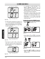
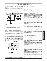
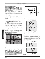
Page 58: ...parameter 15 Fig 7 22 has been activated Fig 7 22 Press keys 11 and 13 Fig 7 20 at the same time until the value of parameter 15 Fig 7 23 is displayed on the LCD display Fig 7 23 Using keys 12 or 13 i...

Page 59: ...ioned during installa tion Press button for more than 3 seconds to enter in Fig 7 25 mode Fig 7 25 0 2 1 8 1 21 15 6 3 9 Press button to display the K REG win dow Fig 7 26 Fig 7 26 It is possible to c...

Page 60: ...h increase or reduction by a unit on the display corresponds to 6 seconds By pressing key 11 Fig 7 27 confirmation of the inserted value is obtained Press keys 11 and 12 Fig 7 27 at the same time to e...

Page 61: ...ncy This time can be changed by a minimum of zero to a maximum of eight and a half min utes by acting on programming both from the panel controls and the remote control Enter the programming mode by p...

Page 62: ...turn to the parameters list Fig 7 37 Press keys 11 12 13 Fig 7 35 at the same time for 10 seconds to exit the pro gramming mode Programming using the REMOTE control Act on the programming of the REMOT...

Page 63: ...tions and Fig 5 1 on page 33 of this manual To carry out a combustion check refer to the instructions given in the section Combustion analysis check to page 73 of this manual Reference figures are giv...

Page 64: ...the useful central output does not prevent the boiler firing at maximum rate for domestic hot water production Refer to Fig 7 44 and determine the correct Value appertaining to the output required fo...

Page 65: ...he setting opera tion it is important to fill update the table Fig 7 49 This to allow a correct setting of this boiler in case of replacement of the main control p c b PARAMETER DIGIT VALUES Boiler ty...

Page 66: ...n the LCD display Fig 7 52 Fig 7 52 Press keys 11 and 12 Fig 7 50 at the same time to exit without changing the val ue return to the parameters list Fig 7 51 Scroll the various parameters using keys 1...

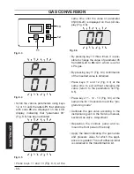
Page 67: ...Fig 8 1 Fig 8 1 A B C Carry out gas conversion by correctly re placing the gas restrictor Fig 8 2 refer ring to the Technical Data section page 22 Advance Plus 16S ERP page 25 Advance Plus 25S ERP an...

Page 68: ...om 00 G20 to 05 G31 which is ok for LPG gas By pressing key 11 Fig 8 3 confirmation of the inserted value is obtained Press keys 11 and 12 Fig 8 3 at the same time to exit without changing the value r...

Page 69: ...tion switch adjacent to the appliance and turn off the gas cock before carrying out any procedures whatsoever for cleaning maintenance opening or dismantling boiler panels The Engineer should complete...

Page 70: ...pring towards the internal side of the boiler and simultaneously push the front case panel D until it is completely hold in place Fig 9 4 step 1 2 Repeat the same operation on the op posite side of th...

Page 71: ...urner unit 34 in Fig 9 9 Fig 9 9 J K L 34 M N O P Q Remove the body s front panel and turn the controls panel see Dismantling the external panels to page 69 Unscrew the connector L remove the fix ing...

Page 72: ...using a suction device The burner does not require any particular maintenance just remove dust using a bris tle brush More specific maintenance will be valuated and carried out by an Authorised Assist...

Page 73: ...see Setting the boiler chimney sweep function to page 75 Make sure that the ambient thermostat is in the position call for heat Withdraw an abundant amount of d h w by opening the faucets Check the c...

Page 74: ...require any particular mainte nance but just check That no solid deposits have formed if so remove them That the condensate drain piping is not clogged Unscrew the plug to clean inside the pipe Fig 9...

Page 75: ...on at minimum output in domestic hot water mode Press keys 12 and 13 Fig 9 18 at the same time until the LCD display displays the letters LP that alternate with the heat ing water temperature value e...

Page 76: ...maximum output Press further key 13 to vary again the output in chimney sweep mode when the LCD display displays the letters dP that alternate with the heating water tempera ture value e g 99 the chi...

Page 77: ...nstigate the boiler guarantee the boiler needs to be registered with the manufacturer within one month of the installation To maintain the boiler guarantee it is essential that the boiler is serviced...

Page 78: ...terlock Provided ALL SYSTEMS The system has been flushed and cleaned in accordance with BS7593 and boiler manufacturer s instructions Yes What system cleaner was used What inhibitor was used Quantity...

Page 79: ...gister No Record At max rate CO ppm AND CO At min rate Where Possible CO ppm AND CO Comments Signature SERVICE 04 Date Engineer name Company name Telephone No Gas safe register No Record At max rate C...

Page 80: ...1796222012 17962 2201 2 0616 80A5 UK Biasi UK Ltd Commercial Road Leamore Enterprise Park WALSALL WS2 7NQ Sales Tel 01922 714600 Tech Service Tel 01922 714636 www biasi co uk 08 02 2016 N...

Reviews: