


CH – PE – WT100
B-
N
OTE TECNICHE PER L
’
INSTALLAZIONE
/I
NSTRUCTIONS FOR THE ISTALLER
N
OTAS TÉCNICAS PARA LA INSTALACIÒN
/
Edition 07–2003
– 48 –
I
UK
E
10.7 P
ULIZIA DEL CORPO
CALDAIA E DEL
BRUCIATORE
10.7 C
LEANING BOILER
BODY AND THE
BURNER
10.7
LIMPIEZA DEL
CUERPO DE LA
CALDERA Y DEL
QUEMADOR
1 Scollegate la caldaia dalla
rete elettrica agendo sul
pulsante di spegnimento
caldaia e sull’interruttore
bipolare dell’impianto.
2 Chiudete il rubinetto gas
posto nella parte posteriore
della caldaia.
3 Togliere il pannello frontale
e il pannello superiore
della carrozzeria.
4
Svitare il girello (C in fig.
10.2) e le quattro viti fissa
bruciatore (D in fig. 10.2),
quindi estrarlo
frontalmente.
1 Disconnect the boiler from
the electricity mains by
means of the boiler OFF
push button and the
system’s bipolar switch.
2 Close the gas cock behind
the boiler.
3 Remove the front and top
casing panel.
4
Unscrew the ring (C in fig.
10.2) and the four burner
securing screws (D in fig.
10.2) and pull it out front
ways.
1 Desconectar la caldera de
la red eléctrica actuando
sobre el botón de apagado
de la caldera y el
interruptor bipolar de la
instalación.
2 Cerrar el grifo de gas
situado en la parte
posterior de la caldera.
3 Retirar los paneles frontal
y superior de la carcasa.
4
Desenroscar la arandela
(C en la fig. 10.2) y aflojar
los cuatro tornillos de
fijación del quemador (D
en la fig. 10.2), luego
sacarlo frontalmente.
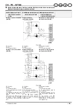
Fig. 10.2
5
Spazzolare con un
pennello le rampe esterne
del bruciatore e rimuovere
eventuali depositi di
polvere all’interno delle
stesse.
6 Svitare le due viti (E in fig.
10.2) della cappa e
rimuovere il coperchio di
servizio, pulite con uno
scovolo il corpo caldaia.
7 Rimontate il tutto ed
eseguite la prova di tenuta
gas.
5 Use a brush to clean the
outside burner ramps and
remove any dust deposits
from inside them.
6 Unscrew the two screws (E
in fig. 10.2) of the hood
and remove the service lid;
clean the boiler body with a
tube-brush.
7
Reassemble everything
and test for gas leaks.
5 Cepillar con un pincel las
rampas exteriores del
quemador y retirar los
eventuales depósitos de
polvo al interior de éstas.
6 Aflojar los dos tornillos (E
en la fig. 10.2) de la
campana y retirar la tapa,
luego limpiar con un cepillo
el cuerpo de la caldera.
7
Volver a montarlo todo y
realizar la prueba de
estanquidad del gas.
10.8 D
ISPOSITIVO DI
CONTROLLO FUMI
10.8 F
LUE GAS CONTROL
DEVICE
10.8 D
ISPOSITIVO PARA
EL CONTROL DE LOS
HUMOS
La caldaia è equipaggiata con
un dispositivo di controllo
della evacuazione dei prodotti
della combustione.
Nel caso di immissione
nell’ambiente dei gas
combusti (ostruzione o
inefficienza del condotto di
scarico dei fumi), tale
dispositivo interrompe
l’alimentazione del gas alla
The boiler is equipped with a
combustion product
evacuation control device.
Should the combusted gas be
let into the atmosphere (due
to clogging or ineffectiveness
of the flue) this device will
stop gas being supplied to the
boiler and consequently stop
it working.
If this device triggers often it
humos
La caldera está equipada con
un dispositivo para el control
de la evacuación de los
productos de la combustión.
En caso de que en el
ambiente se difundan los
gases de la combustión
(obstrucción o ineficacia del
conducto de evacuación de
los humos), este dispositivo
Summary of Contents for 25 CH
Page 2: ......