background image

INSTALLATION MANUAL

ENGLISH

12) USE OF THE AUTOMATION

Since the automation may be remote controlled either by radio or a Start 
button, it is essential that all safeties are checked frequently.
Any malfunction should be corrected immediately by a qualified specialist.
Keep children at a safe distance from the field of action of the automation.

13) THE CONTROLS

With the automation the gate has a power driven opening and closing. The 
controls can come in various forms (i.e. manual, remote controlled, limited 
access  by  magnetic  badge,  etc.)  depending  on  needs  and  installation 
characteristics. For details on the various command systems, consult the 
specific instruction booklets.
Anyone using the automation must be instructed in its operation and con-
trols.

14) MAINTENANCE

When  carrying  out  maintenance  operation  on  the  controller,  disconnect 
it from the mains power supply. The actuator does not require periodical 
maintenance operations.
•   Check the safety devices of the gate and automation.
•   Periodically check the pushing force and correct the value of the electric 

torque in the control board if necessary.

•   In  case  of  unsolved  operation  failures,  disconnect  the  unit  from  the 

mains power supply and ask for the intervention of qualified personnel 
(installer).

  When the unit is out of order, activate the manual release to perform 

manual opening and closing manoeuvres.

•  

WARNING!

 Grease the worm screw every two years. Recommended 

grease type: 

G885

.

15) NOISE

The aerial noise produced by the gearmotor under normal operating condi-
tions is constant and does not exceed 70dB(A).

16) SCRAPPING

Materials must be disposed of in conformity with the current regulations. 
In case of scrapping, the automation devices do not entail any particular 
risks or danger.  In case of recovered materials, these should be sorted out 
by type (electrical components, copper, aluminium, plastic etc.).

17) DISMANTLING 

When the automation system is disassembled to be reassembled on another 
site, proceed as follows: 
•  Disconnect the power supply and the entire electrical installation. 
•  Remove the gearmotor from its fixing base. 
•  Disassemble the control panel, if separate, and all installation compo-

nents.

•  In the case where some of the components cannot be removed or are 

damaged, they must be replaced. 

18) TROUBLES AND SOLUTIONS
18.1) Incorrect operation of gearmotor

Check for the presence of power supply to the gearmotor using a suitable 
instrument after opening or closing commands have been given.
If the motor vibrates but does not turn, the causes could be the following:
a)  incorrect connection of the C common wire, (it is always light blue).
b)  operation  capacitor  not  connected  to  the  terminals  on  the  control 
board.
c)  if the moving direction of the leaf is opposite to the right one, invert the 
motor running connections.

LIMITING DEVICES: 

If the time set on the control unit is insufficient, the 

leaves might not complete their run.
Slightly increase the working time on the control unit.

18.2) Incorrect operation of the electrical accessories

All control and safety devices can cause, in case of failure, malfunctioning 
or stoppage of the automation.
To identify the failure, it is advised to disconnect all the devices of the auto-
mation one by one until the one causing the problem is found.
After fixing or replacing the defective device, reset all the devices previously 
disconnected. Refer to the relevant instruction manual for all the devices 
installed on the automation.

WARNINGS
Correct controller operation is only ensured when the data contained 
in the present manual are observed. The company is not to be held 
responsible for any damage resulting from failure to observe the 

installation standards


and the instructions contained in the present 

manual.
The descriptions and illustrations contained in the present manual are 
not binding. The Company reserves the right to make any alterations 
deemed appropriate for the technical, manufacturing and commercial 
improvement of the product, while leaving the essential product fea-
tures unchanged, at any time and without undertaking to update the 
present publication.

PHOBOS N L _beta test - 

11

D811609_beta test

Summary of Contents for PHOBOS N L

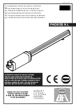
Page 1: ...F D E P PHOBOS N L Via Lago di Vico 44 36015 Schio VI Tel naz 0445 696511 Tel int 39 0445 696533 Fax 0445 696522 Internet www bft it E mail sales bft it AUTOMAZIONI A PISTONE PER CANCELLI A BATTENTE E...

Page 2: ...PHOBOS N L _beta test D811609_beta test...

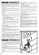
Page 3: ...za tecnica o comunque da persona con qualifica similare in modo da prevenire ogni rischio Fig 1 USER S MANUAL ENGLISH Thank you for buying this product our company is sure that you will be more than s...

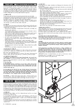
Page 4: ...portail Pour r tablir le fonctionnement motoris tourner la cl dans le sens contraire et remettre le couvercle sa place 4 ENTRETIEN ET DEMOLITION L entretien de l installation doit tre effectu r guli r...

Page 5: ...aci n de poner al d a esta publicaci n ATENCION Si el cable de alimentaci n est da ado deber ser sustitui do por el constructor o por su servicio de asistencia t cnica o en todo caso por persona cuali...

Page 6: ...bambini onde evitare azionamenti involontari dell automazione L utilizzatoredeveevitarequalsiasitentativodiinterventooriparazione e rivolgersi solo a personale qualificato Tutto quello che non espress...

Page 7: ...e la sezione per una lunghezza dei cavi di alimentazione fino a 100 metri per lunghezze superiori calcolare la sezione per il carico reale dell automazione Quando le lunghezze dei collegamenti ausili...

Page 8: ...ta per essere poi rimontata in altro sito bisogna Togliere l alimentazione e scollegare tutto l impianto elettrico Togliere il motoriduttore dalla base di fissaggio Smontare il quadro di comando se se...

Page 9: ...dio control or other control devices out of children s reach in order to avoid unintentional automation activation The user must avoid any attempt to carry out work or repair on the automation system...

Page 10: ...evices in compliance with the previously mentioned electrical installation standards Fig 13 shows the number of connections and the cross section for power supply cables having a length of approximate...

Page 11: ...as follows Disconnect the power supply and the entire electrical installation Remove the gearmotor from its fixing base Disassemble the control panel if separate and all installation compo nents In th...

Page 12: ...merl utilisateurdel installationsurlessyst mesdecommandeap pliqu s et sur l ex cution de l ouverture manuelle en cas d urgence Ne pas permettre des personnes et des enfants de stationner dans la zone...

Page 13: ...l op rateur il est obligatoire d utiliser les but es d arr t FA tant en ouverture qu en fermeture comme indiqu dans la fig 11 6 PR DISPOSITION DE L INSTALLATION LECTRIQUE Pr disposerl installation lec...

Page 14: ...e ATTENTION Graisser la vis sans fin tous les deux ans Graisse conseill e G885 15 BRUIT Le bruit a rien produit par le motor ducteur dans des conditions d utilisation normales est constant et ne d pas...

Page 15: ...eich der Anlage zu verweilen Keine Fernbedienungen oder andere Steuerungsvorrichtungen in Reichweite von Kindern liegenlassen Sie k nnten die Anlage verse hentlich in Gang setzen Der Betreiber hat jed...

Page 16: ...estigen wie in den Abb 6 und 7 ausgewiesen Bei Toren die sich auf einer geneigten Fl che bewegen ffnung nach innen in Richtung eines ansteigenden Weges l sstsichderAntriebumdieH chstwerteausAbb 7imVer...

Page 17: ...ACHTUNG Die Schnecke muss alle zwei Jahre gefettet werden Empfohlene Fettsorte G885 15 L RM DasvomGetriebemotorerzeugteLuftger uschistunternormalenBetriebsbe dingungen gleichbleibend und berschreitet...

Page 18: ...ura manual en caso de emergencia No permitir que personas o ni os estacionen en el campo de acci n del automatismo No dejar radiomandos u otros dispositivos de mando al alcance de los ni os para evita...

Page 19: ...ar los topes FA tanto en apertura como en cierre como indica la fig 11 ATENCION Los topes de las hojas deben colocarse en el suelo tanto en cierre como en apertura Evitan que el v stago del servomotor...

Page 20: ...os 70dB A 16 DEMOLICION La eliminaci n de los materiales debe hacerse respetando las normas vi gentes En el caso de demolici n de un automatismo no existen particulares peligros o riesgos que deriven...

Page 21: ...crian as de ficarem paradas na rea de ac o da automatiza o N o deixe radiocomandos ou outros dispositivos de comando ao alcance de crian as para evitar accionamentos involunt rios da automatiza o O ut...

Page 22: ...AS FOLHAS AO CH O Para o funcionamento correcto do onador obrigat rio utilizar bloqueios de paragem FA quer na abertura quer no fecho como indicado na fig 11 6 PREDISPOSI O DA INSTALA O EL CTRICA Prep...

Page 23: ...i n es constante y no supera los 70dB A 16 DESTRUI AO Aten o Valer se exclusivamente de pessoal qualificado A elimina o dos materiais deve ser feita respeitando se as normas vi gentes No caso de destr...

Page 24: ...4 117 120 122 123 160 102 105 108 111 112 116 118 121 122 170 101 105 108 111 111 115 117 120 120 180 101 104 107 109 111 114 116 118 119 190 100 103 106 108 110 113 115 117 117 200 99 103 106 108 109...

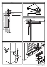
Page 25: ...Fig 4 Fig 5 Fig 3 Fig 7 P b 65 a b 925 1080 F F B S R A Fig 6 PHOBOS N L _beta test 25 D811609_beta test...

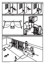
Page 26: ...S P I R Q AL 3x1mm2 2x1 5mm2 3x1 5mm2 RG58 Fte T 2x1mm 2 3x1 5mm 2 3x1 5mm 2 4x1mm 2 4x1mm 2 2x1 5mm2 2x1mm2 3x1mm2 Sinistra Left Gauche Links Izquierda Esquerda Destra Right Droite Rechts Derecha Di...

Page 27: ...Fig 14 Fig 16 Fig 17 Fig 15 1 2 m m 1 2 m m EBP PHOBOS N L _beta test 27 D811609_beta test...

Page 28: ......

Reviews: