13
2.0 SPECIFICATION
2.1 POWER SUPPLY
The Williams Data Logger (W.D.L) is supplied with a 12VDC
from a Switch-mode power supply (S.M.P.S).
2.2 PRINTER PAPER ROLL
The W.D.L is connected to a thermal printer which requires a
(57mm / 2.24” with a diameter not greater than 40mm)
thermal printer paper roll.
2.3 I.P (INGRESS PROTECTION) RATING
The W.D.L and printer module are protected by a
polycarbonite hinged cover that has an IP rating of 65 when
in the closed position.
2.4 HARDWARE AMBIENT OPERATING LIMITS
The printer and W.D.L are guaranteed to operate in an
ambient temperature between
-10°C / 14°F and 50°C / 122°F
in a
15 to 80% of relative humidity
.
3.0 OPERATION OVERVIEW
3.1 DISPLAYS DURING CABINET OPERATION
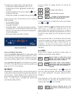
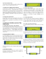
When an operation cycle (e.g.- timed blast) has been
initiated, the W.D.L will display information relevant to that
cycle (as shown below).
3.1.1 Timed and Temperature Based Blast Cycle
The screens shown below will be displayed during a timed
blast and temperature based blast cycle. The W.D.L can still
be used during operation (e.g.- parameters can be accessed,
stored data can be viewed etc.).
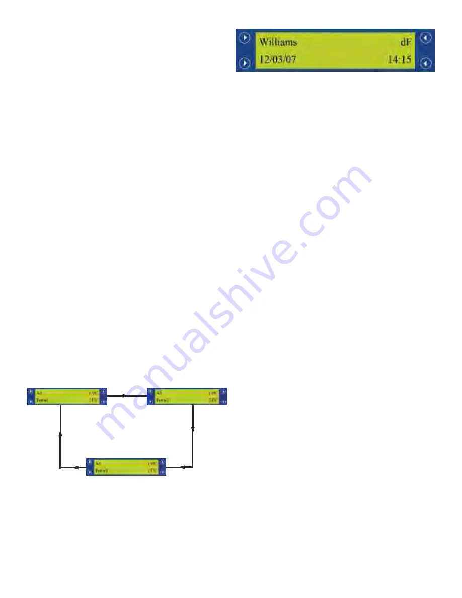
3.1.2 Defrost
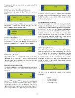
The screen shown below is displayed during a defrost cycle.
The W.D.L can still be used during operation (e.g.-
parameters can be accessed, stored data can be viewed
etc.).
3.2 DATA RECORDING MODE
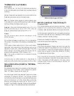
The W.D.L is used to record the controllers status and the
temperature measured by the selected probe (through a
parameter) every 5 seconds.
3.2.1 Alarms
If an alarm occurs, the time, date, controller status and
temperature are recorded into the W.D.L’s memory and
printed immediately on a ticket.
- Power Failure
=
PWF
- High Temperature
=
HI_T
- All Other Alarms
=
ALM
3.2.2 Blast Mode (Time)
The time, date and temperature of the Air probe at the
beginning and the end of the blast cycle are recorded.
3.2.3 Blast Mode (Temperature)
The threshold duration is recorded, i.e. the time taken for the
food probe temperature to reach the setpoint from the
highest recorded temperature.
If a blast cycle is not active, the average hourly temperature
and any alarms are stored while the recording is taken.
3.3 DATA STORAGE
Data recorded is stored on the W.D.L automatically and can
be printed at anytime manually.
3.4 DISPLAY MODE INDICATIONS
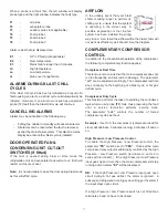
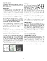
The current cabinet status will be displayed in the top
right-hand corner of the default display screen during
operation.
3.4.1 Standby
When the W.D.L is in standby, ‘
- - -
’ will be displayed.
3.4.2 Temperature Logging
The current internal cabinet temperature (e.g.
‘39°F / 4°C’
)
will be displayed.
3.4.3 Defrost
A defrost or recovery period is indicated by
‘dF’
being
displayed (see section 3.1.2 for more details).
3 secs
3 secs
3 secs
Summary of Contents for Williams WBC110
Page 12: ...12 by OPERATING ENGINEERS MANUAL for WILLIAMS DATA LOGGER W D L with PRINTER MODULE...
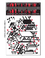
Page 20: ...20 PARTS LIST FOR A WBC35...
Page 21: ...21 PARTS LIST FOR A WBC60...
Page 22: ...22 PARTS LIST FOR A WBC75...
Page 23: ...23 PARTS LIST FOR A WBC110...
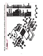
Page 24: ...24 PARTS LIST FOR A WMBC175 220 350 CONTROLLER WITH POD PRINTER...
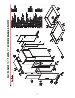
Page 25: ...25 PARTS LIST FOR A WMBC175 220 350 PANEL LAYOUT...
Page 26: ...26 PARTS LIST FOR A WMBC175 220 350 EQUIPMENT...
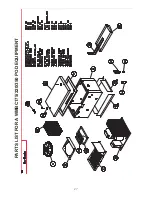
Page 27: ...27 PARTS LIST FOR A WMBC175 220 350 POD EQUIPMENT...
Page 28: ...28 PARTS LIST FOR A WMBC175 220 350 PANEL LAYOUT...
Page 29: ...29 PARTS LIST FOR A WMBC350 EQUIPMENT...
Page 30: ...30 PARTS LIST FOR A WMBC480 660 PANEL LAYOUT...
Page 31: ...31 PARTS LIST FOR A WMBC480 660 CONTROL PANEL WITH PRINTER POD...
Page 32: ...32 PARTS LIST FOR A WMBC480 EQUIPMENT LAYOUT...
Page 33: ...33 PARTS LIST FOR A WMBC660 EQUIPMENT LAYOUT...
Page 34: ...34 PARTS LIST FOR A WMBC480 660 POD EQUIPMENT...
Page 35: ...35 PARTS LIST FOR A WMBC480 660 PANEL LAYOUT...
Page 49: ...49...
Page 50: ...50...
Page 51: ...51...


