7
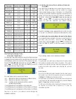
When a probe is at fault then the left window will display
probe type and the right window indicates the fault type.
T1
-
air probe
T2
-
evaporator probe
T3
-
auxiliary probe (not applicable)
T4
-
Food probe 1
T5
-
Food probe 2
T6
-
Food probe 3
Alarm codes that are displayed are:
E1
-
HP / LP fault (not applicable)
E2
-
Over temperature
E3
-
Mains failure longer than 3 minutes
Hi
-
High temperature
Lo
-
Low temperature
or
-
probe over range failure
ALARMS DURING BLAST CHILL
CYCLES
If the blast chill cycle has been terminated as a result of a
fault causing an alarm, a defrost cycle will automatically be
initiated. However, it an alarm occurs such as evaporator
probe (T2) fault then the blast chill cycle will continue.
CANCELLING ALARMS
Alarms may be cancelled in the following way:
-
Putting the cabinet in standby will cancel all alarms
-
All alarms can be reset when the fault is removed,
except the mains failure alarm. This alarm remains
displayed until another blast cycle is initiated.
DOOR OPERATED FAN &
CONDENSING UNIT CUT-OUT
SWITCHES (if fitted)
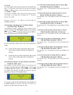
If the door is opened during blast or store mode the
refrigeration unit and evaporator fans will cut out. Both will
restart on closure of door.
Note:
it is not advisable to open the door during blast mode
as this will effect cycle.
AIRFLOW
In the unlikely event that your blast
chiller is taking longer to perform its
chilling cycle, ensure that the system
is operating in the correct way.
A
possible explanation is that the fan
system has been installed the wrong
way round. As a result the airflow within the blast chiller will
not work as effectively as it should. See the diagram.
COMPLEMENTARY COMPRESSOR
CONTROL
In addition to the conventional operation of the compressor,
the following complementary function applies;
Compressor Rest Time
This function is to ensure that the main compressor does not
run too frequently, and succumb to damage. The parameter
“crt”
can be adjusted accordingly. The compressor rest time
does not apply to the beginning of a blast cycle or hot gas
defrost cycle.
Compressor Duty Cycle
This function performs the task of overriding the controller’s
logic when an air probe
(T1)
fails, thus preserving the food
until
a
service
technician
performs
service
work.
The parameter
“cdc”
controls the number of forced
compressor cycles per hour.
Example:
If set to 5, the compressor (compressor used for
store) will alternate, 5 minutes running, 5 minutes off and so
on.
High Pressure / Low Pressure Control
To enable the High Pressure / Low Pressure control, the
parameter
“PS”
must be set to
“YES”
. Once set the main
compressor relay output is additionally controlled by the High
Pressure / Low Pressure switch (terminals L3 and L2 in
series with terminal L1). If the High Pressure / Low Pressure
input goes open circuit, then the main compressor will stop
running and an alarm
“E1”
will be displayed.
NB:
If the High Pressure / Low Pressure input goes open
circuit during a hot gas defrost, the alarm is ignored. A
subsequent refrigeration cooling cycle will trigger the alarm if
the input stays open circuit.
If a High Pressure / Low Pressure switch is not fitted then
terminals L2 and L3 have to be linked.
Summary of Contents for Williams WBC110
Page 12: ...12 by OPERATING ENGINEERS MANUAL for WILLIAMS DATA LOGGER W D L with PRINTER MODULE...
Page 20: ...20 PARTS LIST FOR A WBC35...
Page 21: ...21 PARTS LIST FOR A WBC60...
Page 22: ...22 PARTS LIST FOR A WBC75...
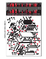
Page 23: ...23 PARTS LIST FOR A WBC110...
Page 24: ...24 PARTS LIST FOR A WMBC175 220 350 CONTROLLER WITH POD PRINTER...
Page 25: ...25 PARTS LIST FOR A WMBC175 220 350 PANEL LAYOUT...
Page 26: ...26 PARTS LIST FOR A WMBC175 220 350 EQUIPMENT...
Page 27: ...27 PARTS LIST FOR A WMBC175 220 350 POD EQUIPMENT...
Page 28: ...28 PARTS LIST FOR A WMBC175 220 350 PANEL LAYOUT...
Page 29: ...29 PARTS LIST FOR A WMBC350 EQUIPMENT...
Page 30: ...30 PARTS LIST FOR A WMBC480 660 PANEL LAYOUT...
Page 31: ...31 PARTS LIST FOR A WMBC480 660 CONTROL PANEL WITH PRINTER POD...
Page 32: ...32 PARTS LIST FOR A WMBC480 EQUIPMENT LAYOUT...
Page 33: ...33 PARTS LIST FOR A WMBC660 EQUIPMENT LAYOUT...
Page 34: ...34 PARTS LIST FOR A WMBC480 660 POD EQUIPMENT...
Page 35: ...35 PARTS LIST FOR A WMBC480 660 PANEL LAYOUT...
Page 49: ...49...
Page 50: ...50...
Page 51: ...51...


