Beverage-Air Williams WBC110 Installation And Operating Manual Download Page 4

4

START-UP

Main Control Breakers

Should the equipment fail to run on initial connection, please

check that all Main Control Breakers (MCBs) are in the “ON”

position at the back of cabinet.

Note:

The “ON” position is

confirmed by red indicators on the MCBs.

Thermometer

The controller is marked in Fahrenheit (°F) or Centigrade (°C)

for the thermometer display. The thermometer should be

checked daily to ensure that the equipment is maintaining the

correct temperature.

If the cabinet is operating at the wrong temperature due to a

default, the cabinet will alarm.

PRINCIPLES OF OPERATION

Williams blast chillers have been designed to quickly reduce

the temperature of food in accordance with Department of

Health guidelines on the chilling of cooked foods.

All

operators should be conversant with Department of Health

publication, Chilled and Frozen Guidelines on Cook-Chill and

Cook-Freeze Catering Systems.

Fast temperature reduction is not brought about by placing

the food in a very cold cabinet like a deep freeze. This would

only dry the food badly and take a very long time to reduce

its temperature to the required level. The secret of fast

temperature reduction is in delivering the correct blast of air

and ensuring correct and unobstructed horizontal air flow

inside the cabinet. This is why the equipment has the option

of soft and hard facility on blast chill.

Exceptions: depending on the density types and sizes

of the portions the chiller might not be capable of

achieving the required guidelines, therefore, the load

and/or depth of the food layers should be reduced. You

may find it necessary to experiment with different

amounts of food and loading methods in order to

achieve the optimum performance with your blast chiller.
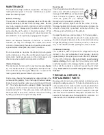
LOADING AND PACKING

Regulations state that product should be placed in the Blast

Chiller within 30 minutes from completion of cooking. The

packaging of food and the way in which it is loaded or placed

within the apparatus can have a significant effect on the time

within which the temperature can be reduced to the required

level and the amount of food which can be processed in each

chilling batch.

When blast chilling always use metal or foil containers which

are good conductors. Plastic or polyurethane containers

insulate the food from the cold air. When chilling unportioned

food we recommend the use of the appropriate pan that is at

least 2

1

/

2

” (63.5mm) in depth. Likewise, placing lids or

covers on food will also increase the chilling time but may be

of some use when processing some delicate foods to avoid

dehydration.

Always load your machine in such a way that it is possible

for the cold air to contact all sides of the containers. Avoid

stacking containers directly on top of one another as this will

drastically extend the chilling time and take special care not

to block the air ducts.

Always load the machine before selecting the blast cycle.

Unless it is unavoidable do not open the door of the machine

while the blast cycle is engaged.

In the case of roll-in rack models, bumper bars are fitted to

the walls inside the machine. This assists in the correct

positioning of the rack(s) so as to avoid blocking the air flow.

FOOD STORAGE TIME

Chilled foods can be stored for up to 5 days at between 32°F

(0°C) and 38°F (3°C).

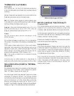
OPERATION OF BLAST CHILLERS

The cabinet is delivered ready to run. Plug (or connect) to the

main power supply and the cabinet is ready for use. Initially

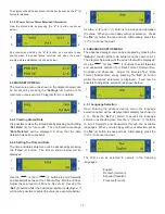
the cabinet will be in standby mode, shown by 3 dashes

( - - -) in both display windows. The cabinet needs to be

pre-chilled (or ran) for at least 30 minutes before being used.

Note:

The control systems employed contain no user

serviceable components. Instructions on setting up the con-

trol panel thermostats are available from the manufacturer.

These should only be reset by a qualified service technician.
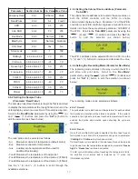
3 BASIC MODES

Timed Cycle Blast

This is the storage temperature at which food can be held

and the blast chiller automatically switches into this mode at

the end of each cycle. Normal storage temperature range is

34°C (1°C) to 37°F (3°C).

Storage Mode

During store mode (with no alarm condition or defrost cycle

running) the left hand window will display the previous blast

cycle duration and the right hand window will display the

store temperature. Some chillers have more than 1 fan

installed; these may not all operate during the storage mode,

Summary of Contents for Williams WBC110

Page 1: ...s WBC35 WBC60 WBC75 WBC110 Roll In Models WMBC175 WMBC220 WMBC350 WMBC480 WMBC660 Provided the instructions in this Operating Manual are read and implemented correctly the optimum performance and reli...

Page 2: ...s continued Door Operated Fan and Condensing Unit Cut Out Switches Airflow Compressor Control Page 8 Thermostats and Probes Data Logger and Printer Miscellaneous Functionality Page 9 Maintenance Clean...

Page 3: ...hours before switching ON Ventilation It is essential to ensure that the room in which the cabinet is installed is adequately ventilated Refrigerators Chillers generate considerable amounts of heat a...

Page 4: ...t of food which can be processed in each chilling batch When blast chilling always use metal or foil containers which are good conductors Plastic or polyurethane containers insulate the food from the...

Page 5: ...ure will be automatically printed and saved onto the Williams Data Logger FP1 03 FP2 02 4 After a short delay the LED relevant to the probe that has been reinserted into the newly introduced product w...

Page 6: ...defrost the display windows will indicate the following Following a blast chill cycle An alarm condition is present will appear in the left window if power failure happens during defrost mode for a d...

Page 7: ...has been installed the wrong way round As a result the airflow within the blast chiller will not work as effectively as it should See the diagram COMPLEMENTARY COMPRESSOR CONTROL In addition to the c...

Page 8: ...l printer which requires a 2 24 57mm with a diameter not greater than 1 57 40mm thermal printer paper roll The Data Logger retains approximately 7 days worth of data depending on usage by default This...

Page 9: ...en all shelves have been removed remove the racking by lifting up and over the nylon retaining blocks Door Gasket Clean the gasket weekly with warm soapy water and a soft cloth taking care not to dama...

Page 10: ...n time Food thermal conductivity the lower the conductivity the longer the pull down time Food specific heats the higher the specific heat the longer the pull down time Container surface area the smal...

Page 11: ...essive amount of warm product loaded in cabinet Allow adequate time for product to cool down Prolonged door openings or door s ajar Make sure door s are closed when not in use Avoid prolonged door ope...

Page 12: ...12 by OPERATING ENGINEERS MANUAL for WILLIAMS DATA LOGGER W D L with PRINTER MODULE...

Page 13: ...arameters can be accessed stored data can be viewed etc 3 2 DATA RECORDING MODE The W D L is used to record the controllers status and the temperature measured by the selected probe through a paramete...

Page 14: ...e as shown in the diagram directly below The W D L will revert back to the default display automatically after 30 seconds Access the Main Menu refer to diagram below by pressing any button 4 3 MAIN ME...

Page 15: ...w be possible to adjust the value see example below Use the 2 and 1 buttons to increase and decrease the value When you are happy with your selection Press the Ok 4 button to save and exit Alternative...

Page 16: ...tons to increase decrease the value 4 6 ENGINEERING PARAMETERS The engineering parameters are used to control much of the W D L s temperature logging and other advanced functionalities Should these pa...

Page 17: ...to the same value on both the W E B controller and the W D L to enable communication between them Parameter nr of the W E B controller see W E B controller engineer s manual for more details is to hav...

Page 18: ...using the 2 and 1 buttons and pressing the Set 4 button to edit the selection as shown in the diagram below The number of hours worth of stored data to be retained can be adjusted between 1 and 168 U...

Page 19: ...19 by PARTS LISTS WIRING DIAGRAMS and CONTROLLER SET UP for REACH IN and ROLL IN BLAST CHILLERS...

Page 20: ...20 PARTS LIST FOR A WBC35...

Page 21: ...21 PARTS LIST FOR A WBC60...

Page 22: ...22 PARTS LIST FOR A WBC75...

Page 23: ...23 PARTS LIST FOR A WBC110...

Page 24: ...24 PARTS LIST FOR A WMBC175 220 350 CONTROLLER WITH POD PRINTER...

Page 25: ...25 PARTS LIST FOR A WMBC175 220 350 PANEL LAYOUT...

Page 26: ...26 PARTS LIST FOR A WMBC175 220 350 EQUIPMENT...

Page 27: ...27 PARTS LIST FOR A WMBC175 220 350 POD EQUIPMENT...

Page 28: ...28 PARTS LIST FOR A WMBC175 220 350 PANEL LAYOUT...

Page 29: ...29 PARTS LIST FOR A WMBC350 EQUIPMENT...

Page 30: ...30 PARTS LIST FOR A WMBC480 660 PANEL LAYOUT...

Page 31: ...31 PARTS LIST FOR A WMBC480 660 CONTROL PANEL WITH PRINTER POD...

Page 32: ...32 PARTS LIST FOR A WMBC480 EQUIPMENT LAYOUT...

Page 33: ...33 PARTS LIST FOR A WMBC660 EQUIPMENT LAYOUT...

Page 34: ...34 PARTS LIST FOR A WMBC480 660 POD EQUIPMENT...

Page 35: ...35 PARTS LIST FOR A WMBC480 660 PANEL LAYOUT...

Page 36: ...MOTE DATA I O L10 L11 L N SWITCH DOOR Whi Red Whi Red Whi Red Whi Red Whi Red Whi Red Link for required voltage B7 HP LP STAT L2 L3 W1 10Amp Q1 1 2 3 4 5 6 K1 W3 W4 P2 P1 2 5mm 13AWG M M E1 W2 1 2 G Y...

Page 37: ...4 1 2 W4 7 8 X1 B9 CONDENSOR UNIT E3 E2 E1 E4 VAP TRAY HEATER DEFROST HEATERS F1 DEFROST KLIXON DOOR HEATER 4kW CONTACTOR K1 W1 W2 W3 W4 W5 W6 W7 W8 W9 FRONT CONTROL PCB INTERFACE REAR MAIN PCB INPUT...

Page 38: ...Brn M1 M Blu G Y Blk Brn M2 M Blu G Y Blk Brn M3 L7 C1 C2 C3 Blu Brn Blk G Y Blu Brn Blk G Y Blu Brn Blk G Y Blu Brn Blk G Y G G G C4 P2 X1 G M Blu G Y Blk Brn M4 17 17 18 18 17 18 C1 15 C2 15 C3 15...

Page 39: ...ONS USE COPPER CONDUCTORS ONLY 9 10 2 x 2 5mm 13AWG E1 VAP TRAY HEATER C1 C4 1 5uF CAPACITOR E2 E4 E5 CONDENSING UNIT DEFROST HEATERS DOOR HEATER DEFROST KLIXON F1 K1 7 5kW CONTACTOR REAR MAIN PCB INP...

Page 40: ...p Q2 1 2 3 4 5 6 K1 1 2 3 R1 S1 T1 X1 a r e n o t b l a s t f a n e a r t h c o n d u c t o r s s h o w n f o r c l a r i t y MODELS ONLY 1 2 3 3 M Gn Wh Ye Bk Bl Br M1 3 M Gn Wh Ye Bk Bl Br M2 3 M Gn...

Page 41: ...c l a r i t y MODELS ONLY 3 5 0 M 3 10Amp Q3 S2 T2 10Amp Q2 T1 3 M Gn Wh Ye Bk Bl Br M1 3 M Gn Wh Ye Bk Bl Br M2 3 M Gn Wh Ye Bk Bl Br M3 1 2 3 W2 E1 4 4 4 4 5 5 5 5 6 6 6 6 6 G 5 COPPER CONDUCTORS O...

Page 42: ...2 3 3 M Gn Wh Ye Bk Bl Br M1 3 M Gn Wh Ye Bk Bl Br M2 3 M Gn Wh Ye Bk Bl Br M3 1 2 3 2 1 3 2 3 2 3 1 W3 1 X2 E1 4 4 4 4 5 5 5 5 6 6 6 6 6 G 5 4 5 6 G 4 5 6 G R2 S2 T2 4 G Y 5 6 4 G Y 6 5 X3 X3 1 X3 1...

Page 43: ...mp Q2 1 2 3 R1 S1 T1 X1 2 3 1 2 3 3 M Gn Wh Ye Bk Bl Br M1 3 M Gn Wh Ye Bk Bl Br M2 3 M Gn Wh Ye Bk Bl Br M3 2 1 3 2 3 2 3 1 1 X2 10Amp Q3 E1 4 4 4 4 5 5 5 5 6 6 6 6 6 G 5 4 5 6 G 4 5 6 G R2 S2 T2 4 G...

Page 44: ...VIEW P4 PRINTER MODULE P2 REAR MAIN PCB INPUT OUTPUT W E B W1 PRINTER DATA CABLE WITH PLUG W2 SERIAL COMMUNICATION CABLE G1 SWITCH MODE POWER SUPPLY G1 Note Unless Stated All Wires Are 1 0mm 17AWG PO...

Page 45: ...ton The initial parameters are as follows Scroll to PASS CODE and enter127 for extended parameters using the and butt ons Enter the pass code by pressing the set button an d using the and buttons The...

Page 46: ...ffset K 0 Frh Freeze Stat Hysteresis K 3 oS3 Auxiliary probe offset K 0 rcd Rapid Cool down Delay min 0 oS4 Food probe 1 offset K 0 dFr Defrost Frequency per day 4 oS5 Food probe 2 offset K 0 dto Defr...

Page 47: ...Frh Freeze Stat Hysteresis K 3 oS3 Auxiliary probe offset K 0 rcd Rapid Cool down Delay min 0 oS4 Food probe 1 offset K 0 dFr Defrost Frequency per day 4 oS5 Food probe 2 offset K 0 dto Defrost Time O...

Page 48: ...sor malfunction and will void warranty Although cleaning requirements vary in accordance with the operation of various products Beverage Air recommends a minimum monthly cleaning ADDITIONAL TWO 2 YEAR...

Page 49: ...49...

Page 50: ...50...

Page 51: ...51...

Page 52: ...7111 Email info williams refrigeration co uk Website www williams refrigeration co uk by USA Blast Chiller O M Rev 1 April 2013 S A NITATION LIST E D INTERTEK 9900508 CM LISTED INTERTEK 9900508 CM BEV...

Reviews: