46
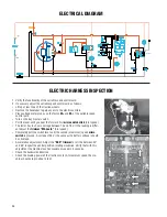
ELECTRICAL DIAGRAM
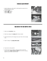
1. Verify the functionality of the variable speed control card.
2. If necessary adjust the variable speed control card as follows:
• Lift up at least one of the traction wheels.
• Remove the handlebar to gain access to the electric controls.
• Place voltage meter probes on the faston
M+
and
M-
of the variable speed
control card.
• Turn on the key master switch.
• Pull the lever until you hear the forward fi rst
micro switch click
(fi rst speed).
• The tester has to show a voltage between 14 and 15 V. If the reading is differ-
ent adjust the
trimmer “MA Lenta”
(fi rst speed).
• Completely pull the switch lever until the second (maximum) speed
micro
switch
is pressed. A voltage of 24 V (the same as the battery voltage) should
be observed.
• Acceleration adjustment: Adjust the
“ACC” trimmer
to let it be between 30°
and 45° respect the central position rotating clockwise. Verify that with this
adjustment the machine reaches maximum speed in 4 seconds.
• Check the backwards direction.
• Check the braking power of the traction motor. At maximum speed the ma-
chine should stop in about 3 feet.
ELECTRIC HARNESS INSPECTION
VACUUM
MOTOR
Summary of Contents for Stealth ASD26BT
Page 36: ...36 SOLUTION CONTROL DIAGRAM 11 23 9 19 21 13 20 6 5 15 16 4 1 22 10 3 14 8 1 8 2 17 12 18 2 ...
Page 44: ...44 ELECTRICAL DIAGRAM ...
Page 54: ...54 ...
Page 55: ...55 ...


