47
Configuring Bypass pair #1
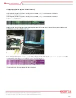
Bypass pair #1 is defined with network Port #3 and Port #4, as the picture below, where Port #3 is connected
internet and Port #4 is connected to a notebook. Also, Bypass pair #1 is now at “
PassThrough
” mode (the
bottom Bypass LED is green) and the network connection is not available.
Now go to the folder
g3bp0
, and issue this command:
echo b > bypass
This will change the status of Bypass pair #1 to “
bypass
” mode, also the bottom Bypass LED will change to
red. As in the picture below, the notebook is now connected to internet.
To reverse this back to “
PassThrough
” mode, simply use this command:
echo n > bypass
This will also turn the bottom Bypass LED back to green.
Summary of Contents for BNX-H110
Page 1: ...1 Security Board BNX H110 Always at the forefront of innovation User Manual...
Page 6: ...6 Chapter 5 Programming Guide 5 1 Bypass Setting 46 5 2 GPIO 50...
Page 7: ...7 Chapter 1 General Information...
Page 11: ...11 Figure 1 1 Board Layout of BNX H110 1 4 Board Layout...
Page 12: ...12 Chapter 2 Preparation...
Page 16: ...16 2 5 Locations Of Jumpers and Connectors...
Page 25: ...25 Factory Default Power Reset Switch SW1 Up Power Switch Reset Switch Down Factory Default...
Page 26: ...26 Chapter 3 Operation...
Page 34: ...34 Chapter 4 BIOS Setup...
Page 40: ...40 CPU Configuration Display CPU Information 4 6 The Chipset Menu...
Page 45: ...45 Chapter 5 Programming Guide...


