22
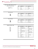
Auto Power Button MCU Firmware
Update Header (JP12)
Pin
Definition
Pin
Definition
1
VPP
2
5VSB
3
GND
4
ICSPDAT
5
ICSPCLK
6
NC
SYS_Fan1 (J1)
Pin
Definition
Pin
Definition
1
GND
2
+12V
3
SYSFanIn1
4
SYSFanOut1
SYS_Fan2 (J2)
Pin
Definition
Pin
Definition
1
GND
2
+12V
3
SYSFanIn2
4
SYSFanOut2
HDMI Connector (J3)
Pin
Definition
Pin
Definition
1
HDMI_BP_TXP0
2
GND
3
HDMI_BP_TXN0
4
HDMI_BP_TXP1
5
GND
6
HDMI_BP_TXN1
7
HDMI_BP_TXP2
8
GND
9
HDMI_BP_TXN2
10
HDMI_BP_CLKP
11
GND
12
HDMI_BP_CLKN
13
NC
14
NC
15
HDMI_SCL
16
HDMI_SDA
17
GND
18
VCC
19
HDMI_HPD
20
GND
Summary of Contents for BNX-H110
Page 1: ...1 Security Board BNX H110 Always at the forefront of innovation User Manual...
Page 6: ...6 Chapter 5 Programming Guide 5 1 Bypass Setting 46 5 2 GPIO 50...
Page 7: ...7 Chapter 1 General Information...
Page 11: ...11 Figure 1 1 Board Layout of BNX H110 1 4 Board Layout...
Page 12: ...12 Chapter 2 Preparation...
Page 16: ...16 2 5 Locations Of Jumpers and Connectors...
Page 25: ...25 Factory Default Power Reset Switch SW1 Up Power Switch Reset Switch Down Factory Default...
Page 26: ...26 Chapter 3 Operation...
Page 34: ...34 Chapter 4 BIOS Setup...
Page 40: ...40 CPU Configuration Display CPU Information 4 6 The Chipset Menu...
Page 45: ...45 Chapter 5 Programming Guide...


