24
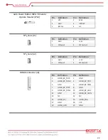
Front Panel Connector (J16)
Pin
Definition
Pin
Definition
1
VCC (+5V)
2
VCC (+5V)
3
HDD_LED
4
GND
5
GND
6
PWRSW
7
SYSRST#
8
GND
9
DEFAULT-
10
GND
11
3Vdual (+3.3V)
12
3Vdual (+3.3V)
13
PCH_GPD11
14
PCH_GPD9
Port 80 Connector (J17)
Pin
Definition
Pin
Definition
1
LPC_AD0
2
VCC3 (+3.3V)
3
LPC_AD1
4
LPC_PLT_RST#
5
LPC_AD2
6
LPC_FRAME#
7
LPC_AD3
8
80H_LPC1CLK_24M
10
GND
GPIO Connector (J18)
Pin
Definition
Pin
Definition
1
SIO_GP67
2
SIO_GP60
3
SIO_GP66
4
SIO_GP61
5
SIO_GP65
6
SIO_GP62
7
SIO_GP64
8
SIO_GP63
9
GND
10
SIO_GPIO_VCC
SATA Power Connector (ATX1)
Pin
Definition
Pin
Definition
1
+12V
2
GND
3
GND
4
VCC (+5V)
Summary of Contents for BNX-H110
Page 1: ...1 Security Board BNX H110 Always at the forefront of innovation User Manual...
Page 6: ...6 Chapter 5 Programming Guide 5 1 Bypass Setting 46 5 2 GPIO 50...
Page 7: ...7 Chapter 1 General Information...
Page 11: ...11 Figure 1 1 Board Layout of BNX H110 1 4 Board Layout...
Page 12: ...12 Chapter 2 Preparation...
Page 16: ...16 2 5 Locations Of Jumpers and Connectors...
Page 25: ...25 Factory Default Power Reset Switch SW1 Up Power Switch Reset Switch Down Factory Default...
Page 26: ...26 Chapter 3 Operation...
Page 34: ...34 Chapter 4 BIOS Setup...
Page 40: ...40 CPU Configuration Display CPU Information 4 6 The Chipset Menu...
Page 45: ...45 Chapter 5 Programming Guide...


