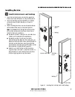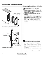
Installation Instructions for 45HM IDH Max® Mortise Locks
BEST ACCESS SYSTEMS
a Division of Stanley Security Solutions, Inc.
15
Installation Instructions for 45HM IDH Max® Mortise Locks
Installing the panel interface module
22
Mount panel interface module
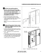
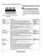
Peel the paper off the adhesive tape affixed to the
back of the panel rail and press the panel rail into
position.
Note:
Mount the panel interface module in the
enclosure with the access control panel/reader interface,
if possible.
23
Connect field wiring from wire transfer
hinge to panel interface module
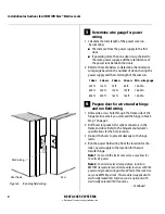
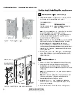
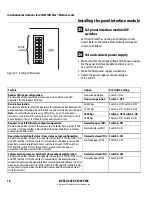
1 Connect the two communication field wires (run from
the wire transfer hinge) to the COM+ and COM–
terminals on the panel interface circuit board.
Note:
The field wire harness leads, connected to the door
side of the wire transfer hinge, are described in the table
below.
2 If you are providing power to the lock through the
panel interface module, connect the two power field
wires (run from the wire transfer hinge) to the 12V and
GND terminals on the panel interface circuit board.
Note:
JP2 and JP3, shown in Figure 23a, are used for
manufacturing purposes only.
3 Connect the RS-485 shield wire to one of the GND
terminals on J1.
Wire
Color
Ground
Black
12 VDC
Red
Com+
Orange
Com–
Green
Figure 22 Mounting the panel interface module
Adhesive
tape
Figure 23a Panel interface circuit board
Figure 23b Connecting field wiring from the
wire transfer hinge
Connect to wire
transfer hinge.


