Installation Instructions for 45HM IDH Max® Mortise Locks
BEST ACCESS SYSTEMS
a Division of Stanley Security Solutions, Inc.
7
Installation Instructions for 45HM IDH Max® Mortise Locks
Installing the trim
11
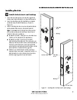
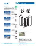
Install wire transfer hinge
Note:
BEST recommends one of the following concealed
electric hinges from Stanley Security Solutions. For more
information, contact your BEST representative.
1 Trim the power and sensor wires that you pulled
through the hinge edge of the door. Leave sufficient
length to connect to the wire transfer hinge and to
allow for future splices.
2 Splice the field wires to the leads on the frame side of
the hinge, following the hinge manufacturer’s
instructions.
3 Splice the power and sensor wires from the lock to the
leads on the door side of the hinge, matching each
lead to its corresponding wire.
Note:
If the lock has an optional RQE status sensor,
splice only the pair of RQE wires for the switch on the
inside of the door, which you identified in Task 9 on
page 6. Put the unused pair of RQE wires in the door.
4 Insert the wires and splice connectors into the holes or
pockets in the door and frame, being careful not to
pinch the wires. Install the wire transfer hinge.
12
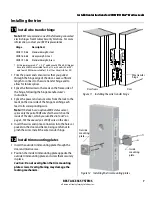
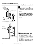
Install trim mounting plates
1 Insert the outside trim mounting plate through the
door and mortise case.
2 Position the inside trim mounting plate opposite the
outside trim mounting plate and screw them securely
in place.
Caution:
Do not overtighten the trim mounting
plate screws. Overtightening may damage the
locking mechanism.
Hinge
Description
†
† All hinges measure 4.5
″ ×
4.5
″
and have a 26D finish. All hinges
have two 24 AWG wires rated for 2 A at 12 or 24 volts (AC or DC)
and four 28 AWG wires rated for 1 A at 12 or 24 volts (AC or DC).
CECB 179-66
Standard weight; steel
CECB 168-66
Heavy weight; steel
CECB 191-66
Standard weight; brass
Figure 11 Installing the wire transfer hinge
Door frame
Wire transfer
hinge
Door
Figure 12 Installing the trim mounting plates
Outside
mounting
plate
Inside
mounting
plate


