background image

Installation Instructions for 45HM IDH Max® Mortise Locks

BEST ACCESS SYSTEMS

a Division of Stanley Security Solutions, Inc.

5

Installation Instructions for 45HM IDH Max® Mortise Locks

Configuring & installing the mortise case

5  Run the sensor wiring from the location of the access 

control panel to the location for the wire transfer hinge.
To match the sensor wire colors, refer to the table below.

7  Pull the field wiring down the wall and through the 

access hole in the frame.

7

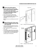
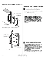
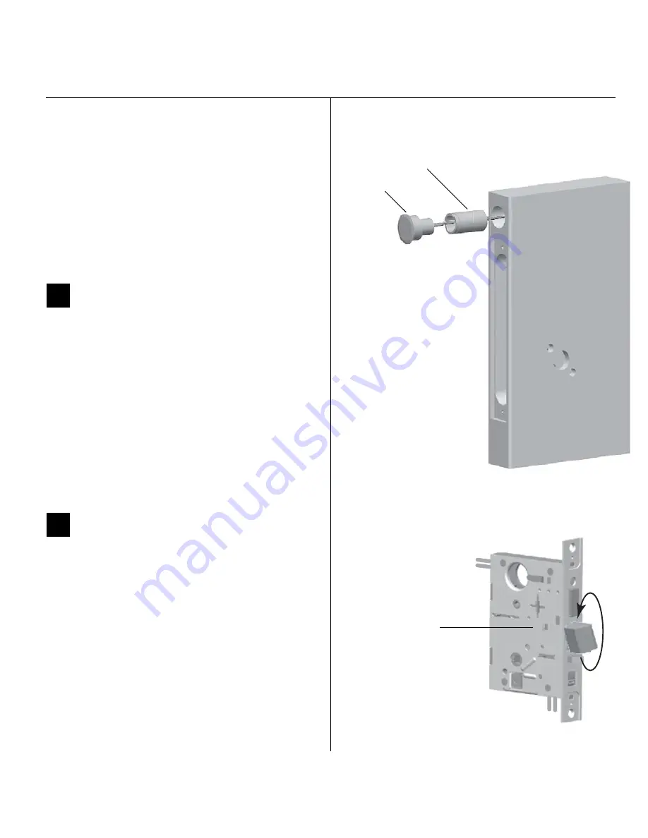
Optional: Install door status switch


(for deadbolt function locks with door 
sensing only)

1  Position the shield on the door status switch with the 

notch facing downwards (towards the mortise pocket).

Caution:  

Make sure the wires are not routed across 

any sharp edges or over any surface that could 
damage its sleeving.

2  Feed the wires for the door status switch into the door 

status switch hole and through the channel into the 
mortise cavity.

3  Insert the door status switch assembly into the door 

status switch hole.

8

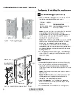
Rotate latchbolt 

(if necessary)

Note: 

If a function specific mortise case was ordered, some 

steps for configuring the case have already been 
performed at the factory.

1  Determine whether you need to rotate the latchbolt to 

match the handing of the door.

Note: 

The angled surface of the latchbolt must contact the 

strike when the door closes.

2  If you need to rotate the latchbolt, insert a flat blade 

screwdriver into the latch access point approximately 
1/2

 into the case and press to extend the latch out of 

the case. See Figure 8.

3  Rotate the latchbolt 180 degrees and allow it to retract 

into the case.

Wire connection

Color

No. of wires

Door status sensor

White

2

Latchbolt status sensor

Purple

2

RQE status sensor

Brown & Orange

2

 Figure 7

Installing the door status switch

Door 
status
switch

Shield

 Figure 8

Rotating the latchbolt

Latch access point

Summary of Contents for 45HM IDH Max Mortise Lock

Page 1: ... lock sensor data from the lock through an RS 485 connection It translates this data into parallel signals which it sends to the access control panel reader interface The panel interface module also translates control signals received from the access control panel reader interface and sends them to the lock The figure below shows the relationship between the components in the IDH Max system Instal...

Page 2: ... guide position the appropriate door template on each side of the door You need to take the bevel into account Tape the templates to the door Figure 1 Aligning the templates Installation template Door edge template Centerline Centerline 1 Identify holes to drill 1 Determine the lock function to be installed 2 Determine the inside and outside hand and bevel of the door 3 See the HolesbyFunction tab...

Page 3: ... to the center of the nearest hinge mortise See Figure 3 Note It may be easier to drill halfway from each side of the door 4 Optional Prepare door for door status switch for deadbolt function locks with door sensing only 1 Locate the centerpoint for the door status switch 2 5 above the top of the faceplate mortise on the edge of the door as shown in Figure 4 2 Drill a 1 diameter hole 1 3 4 deep fo...

Page 4: ...Task 3 Step 1 on page 3 2 Drill holes or pockets for splice connectors in the frame and door Refer to the hinge manufacturer s specifications for the hole location 3 De burr the holes to prevent damage to the hinge leads 4 Run the power field wiring from the location for the lock s power supply to the location for the wire transfer hinge Note 1 To match the lock s wire color use yellow for 12 volt...

Page 5: ... door status switch into the door status switch hole and through the channel into the mortise cavity 3 Insert the door status switch assembly into the door status switch hole 8 Rotate latchbolt if necessary Note Ifafunctionspecificmortisecasewasordered some steps for configuring the case have already been performed at the factory 1 Determine whether you need to rotate the latchbolt to match the ha...

Page 6: ...e the position of a hub toggle remove the toggle screw move the toggle into the desired position and re tighten the screw 10 Install mortise case 1 Remove the faceplate from the mortise case if necessary 2 Insert the mortise case into the mortise cavity while feeding the sensor and solenoid wires into the mortise cavity and out the sensor solenoid wire hole to the inside of the door Note 1 The arm...

Page 7: ...QE wires for the switch on the inside of the door which you identified in Task 9 on page 6 Put the unused pair of RQE wires in the door 4 Insert the wires and splice connectors into the holes or pockets in the door and frame being careful not to pinch the wires Install the wire transfer hinge 12 Install trim mounting plates 1 Insert the outside trim mounting plate through the door and mortise case...

Page 8: ...wn in Figure 13 Caution A malfunction can occur if the cylinder is threaded in too far 2 Secure the cylinder in the mortise case with the cylinder retainer screw 3 Insert the control key into the core and rotate the key 15 degrees to the right 4 With the control key in the core insert the core into the cylinder 5 Rotate the control key 15 degrees to the left and withdraw the key 6 The control key ...

Page 9: ...the DIP switches on the control electronics circuit board located in the inside escutcheon By default switches 1 through 5 are set to ON These switches are for possible future applications By default switches 6 and 7 are set to ON for automatic baud rate detection This setting lets you determinethebaud rate for communicationbetween the lock s control electronics circuit board and the panelinterfac...

Page 10: ... the large opening in the inside trim Figure 15a Feeding the reader wire harness connector from the outside trim through the door Reader wire harness connector Field harness reader wire hole Outside trim Outside of door Figure 15b Connecting the reader wire harness to the control electronics circuit board Reader wire harness connector Sensor wires and solenoid wires Solenoid and sensor wire harnes...

Page 11: ...wire harness the sensor wires and the solenoid wires make sure the wires are not routed across any sharp edges or over any surface that could damage their sleeving or wire insulation 3 Make the solenoid connection and three sensor connections and place the wires into the inside trim Caution When making the sensor connections and solenoid connection make sure there are no loose wire connections whe...

Page 12: ...d secure it with the set screw 3 Push the set screw cap into the set screw hole 4 Tighten the trim mounting screws 5 Turn the knobs to check that they operate smoothly For levers 1 With the handle pointing toward the door hinges insert the outside lever and spindles assembly into the lock from the outside of the door 2 Slide the inside lever onto the inside spindle and secure it with the set screw...

Page 13: ...the core into the cylinder 3 Rotate the control key 15 degrees to the left and withdraw the key Caution The control key can be used to remove cores and to access doors Provide adequate security for the control key 19 Install access door 1 Making sure that the access door does not pinch any wires insert the tabs of the access door into its mating slots and swing the door closed 2 Use a T15 TORX bit...

Page 14: ...someone from forcing the latch open when the door is closed If the incorrect strike is installed a lock in can occur Note The recommended gap between the door and jamb is 1 8 21 Optional Install lock power supply If you are providing a separate power supply for the lock instead of providing power via the panel interface module connect the two power field wires run from the wire transfer hinge to t...

Page 15: ...the wire transfer hinge to the COM and COM terminals on the panel interface circuit board Note Thefieldwireharnessleads connectedtothedoor side of the wire transfer hinge are described in the table below 2 If you are providing power to the lock through the panel interface module connect the two power field wires run from the wire transfer hinge to the 12V and GND terminals on the panel interface c...

Page 16: ...red using DIP switch 8 to serve one of two possible functions Option 1 Door status latchbolt status output Indicates whether the door is secure both the door status and latchbolt status switches are closed or unsecure one or both of these switches are open By default the output is closed to indicate the door is secure Option 2 Door status output Indicates the state of the lock s door status switch...

Page 17: ...ides 0 volts DC for the green LED One wire LED operation Connect the access control panel s reader interface s LED output to the RED terminal The reader s LEDs are controlled as shown below Note The signals provided to the Reader LED input and the Sounder input must be greater than 3 5 volts DC to be interpreted as a 5 volts DC signal Signals with voltage less than 8 volts DC are interpreted as 0 ...

Page 18: ...FF Switch 3 OFF 19200 bps Switch 2 ON Switch 3 OFF 9600 bps Switch 2 OFF Switch 3 ON 2400 bps Switch 2 ON Switch 3 ON Request to exit RQE status output configuration Provides the ability to invert the request to exit RQE status signal If DIP switch 4 is ON the contact is closed when the door knob lever is turned activating the RQE switch Normally open NO Switch 4 ON Normally closed NC Switch 4 OFF...

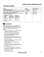
Page 19: ... green reader LED and sounder respond as expected The lock should allow access verifying that the solenoid is working To check that the reader is working view the lock s event history and verify that the information recorded for the token is correct 3 Use an invalid token to attempt to access the lock Confirm that the red reader LED green reader LED and sounder respond as expected The lock should ...

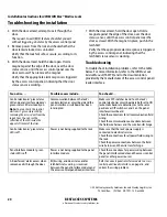
Page 20: ...ce module s green status LED are steadily on Note You can check the control electronic s green status LED by removing the access door from the inside trim You can see the reflection of the LED inside the upper left corner of the trim Communication between the lock s control electronics circuit board and the panel interface circuit board has been interrupted Make sure DIP switches 6 and 7 on the lo...

Reviews: