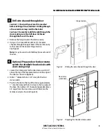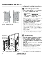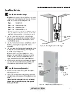
Installation Instructions for 45HM IDH Max® Mortise Locks
BEST ACCESS SYSTEMS
a Division of Stanley Security Solutions, Inc.
4
5
Determine wire gauge for power
wiring
1 Calculate the total length of the power wire run
by summing:
■
The distance from the power supply to the first
door.
■
If powering more than one door daisy-chained to
the same power supply, add the total distance of
the power runs between the doors.
2 Refer to the table below to determine the minimum
wire gauge based on the number of doors sharing the
power supply and the total length of the wire run.
6
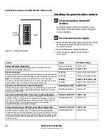
Prepare door for wire transfer hinge
and run field wiring
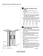
1 Drill a wire access hole through the frame side of the
hinge mortise where you removed the hinge in Task 3,
Step 1 on page 3.
2 Drill holes (or pockets) for splice connectors in the
frame and door. Refer to the hinge manufacturer’s
specifications for the hole location.
3 De-burr the holes to prevent damage to the hinge
leads.
4 Run the power field wiring from the location for the
lock’s power supply to the location for the wire
transfer hinge.
Note 1:
To match the lock’s wire color, use yellow for
12 volts DC power.
Note 2:
To minimize lever temperature, install an
8WTCM (temperature control module) in series with the
power and ground wiring within 20 feet of the lock. Use
only one 8WTCM per lock. This module is supplied with
electrically locked (EL) functions and is optional with
electrically unlocked (EU) functions.
– Continued
1 door
2 doors
3 doors
4 doors
Min. wire gauge
250 ft.
125 ft.
75 ft.
60 ft.
18 AWG
400 ft.
200 ft.
130 ft.
100 ft.
16 AWG
600 ft.
300 ft.
185 ft.
150 ft.
14 AWG
Figure 6
Running field wiring
Door frame
Door
Field wiring


