USER MANUAL 1.2 | B-FORTIS CC-PRIME SERIES
Berghof Automation GmbH | Arbachtalstrasse 26 | 72800 Eningen |
20
5.1.1. Connecting the power supply
CAUTION
Live parts!
Before starting any work on the device, switch off all power feeds, including peripherals.
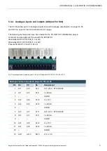
Connect the power supply to plug X1 according to the following table.
Fig. 3: power supply plug X1
Power supply plug X1
Pin
Label
Assignment
1
L+
external 24 V DC (
–15% / +20%) power supply (internal PLC) max. 1 A
2
M
external GND power supply
3
L1+
Digital output DO1
–4 supply, 24 V DC (–20% / +25%) max. 2 A
1
4
L2+
Digital output DO5
–8 supply, 24 V DC (–20% / +25%) max. 2 A
1
5
L3+
Digital output DO9
–12 supply, 24 V DC (–20% / +25%) max. 2 A
1
6
L4+
Digital output DO13
–16 supply, 24 V DC (–20% / +25%) max. 2 A
1
1
Nominal current 2 A at peak load; in case of overload, up to 3 A might flow.

