36
37
Rear view (connection strip at the bottom)
1 Power input DC 12/24V
2 Lan connection
3 Analogue video output
4 Analogue sound output
Side view
1 Digital sound output
2 AV input (via adapter cable)
3 Headphone socket (analogue sound output)
4 Via 2 and 3: CI+ slot for decoding modules
5 2 x USB connection; together up to max. 500 mA, e.g. for hard disks, sound bars or
similar.
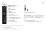
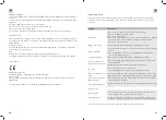
2. POSITION AND FUNCTION OF THE CONTROL BUTTONS AND CONNECTIONS
Position
Tastenbeschriftung
Funktion
1
Input / MENU
• Input signal selection: Satellite, DTV
(antenna, cable), ATV (analog RF), AV, PC,
SCART, Component (YpbPr), DVD, HDMI1,
HDMI2 and Media (via USB).
2
CH+/-
• Program Channel Selection. Press this but-
ton to select the channels or to select the
upper or lower menu in the OSD menu.
3
VOL+/-
• Increase or decrease the volume
• Adjusting the selected menu items in the
OSD menu
4
DVD Play, Eject
• Start DVD
• Eject DVD
5
• Power button: Switches the TV on or off
in standby mode
front bottom right
Remote control
sensor
• Infrared receiver for remote control
front bottom right
Power indicator
• Lights red: Standby
• Lights up green: TV is on
• Not lit: TV is completely without power
right side back
Main switch
• Disconnecting the TV from the power
The on/off switch is located at the back next to the control buttons.
Note/reminder:
If the TV does not receive an HDMI signal after one minute, or does not receive a video
signal for 15 minutes, the TV will automatically switch to standby. The power indicator
LED will then light up red.
1
2
3
4
5
1
2
3
4
5
6
7
8
5 HDMI1 input
6 HDMI2 input
7 RF S2: SAT antenna input
8 RF T2: Cable connection/Terr. antenna input
AV-cable
Plugs into socket 2 (AV input) on the rear of the TV, if required.
Yellow = Video
Red = Right sound channel
White = Left sound channel
1
2
3
4
5
GB
GB


