Bergen Intrepid Magnum Tazer Manual Download Page 4

 
The  first  of  its  kind,  interchangeable  modular  engineered  helicopter  to 
accommodate the beginner to a FAI expert… 
 
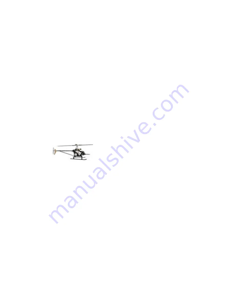
An idea in 1994 to manufacture an interchangeable, modular helicopter, led to 
the  research  and  development  in  1995.    Focusing  on  quality,  engineering 
details,  and  price,  a  prototype  was  produced.    After  extensive  test  flights  and 
fine-tuning, the INTREPID HELICOPTER is now what you see today.  The first 
of its kind, strength combined with simplicity for easy maintenance and flying. 
 
Although  beginners  can successfully  build  and  fly  their  INTREPID,  the  process 
can be made significantly easier with  the help of an experienced modeler and 
instructor pilot.  We recommend that all  beginners join the Academy of Model 
Aeronautics (AMA).  The AMA is a non-profit organization that provides services 
for modelers.  The AMA can help you locate a model aircraft club in your area 
with  an  instructor  pilot  (you  can  also  check  with  your  local  hobby  shop).  
Membership benefits include a monthly magazine and liability insurance.  Many 
flying clubs require an AMA modeler’s license to operate a model on their flying 
field.  For more information on the AMA contact: 


Academy of Model Aeronautics 

 5151 East Memorial Drive 

 Muncie, IN  47302 

 Phone:  (317) 287-1256


Summary of Contents for Intrepid Magnum Tazer

Page 1: ...This manual is for the Intrepid Magnum Tazer and Intrepid Magnum Tazer 800...

Page 2: ...copters by their nature are not positively stable meaning that even if properly assembled and adjusted helicopters will not recover from an unwanted flight attitude nor will they hold any particular o...

Page 3: ...ot and helicopter guru in its early years We would also like to recognize Mike DeMetz for his continuous support and knowledge in electronics and maintenance Staff Chris Bergen Chief Executive Officer...

Page 4: ...fully build and fly their INTREPID the process can be made significantly easier with the help of an experienced modeler and instructor pilot We recommend that all beginners join the Academy of Model A...

Page 5: ...make no warranty express or implied This warranty does not apply to parts damaged by improper assembly modification abnormal service or handling or crashes 2 To take advantage of this warranty the Pu...

Page 6: ...clusion of incidental or consequential damages so the above exclusion may not apply This warranty gives the Purchaser specific legal rights The Purchaser may also have other rights which vary from sta...

Page 7: ......

Page 8: ...sers and the strains placed on airframes and rotor systems from the advent of 3D style of flight The Tazer is the culmination of all of that PLUS PLUS PLUS PLUS the addition of high voltage Li Po s an...

Page 9: ...up to a 720mm blade If you have purchased the Tazer 800 kit then you can run 800 to 810mm blades In either case you will need a blade with a 14mm root and a 4mm bolt hole I have been running the TST 6...

Page 10: ...ng an inventory list and warranty registration Complete the inventory FIRST send us back the final sheet signed signifying that you have received everything If you find something missing complete the...

Page 11: ...more responsive but matched servos are NOT necessary in this NON CCPM machine Let s get started in Bag 1 Slide the aluminum tubes through the plastic crossovers using heat from a hairdryer or monokot...

Page 12: ...put an additional countersunk bolt in this location Building up the frames starts with Bag 2 and assembling the battery trays Both battery trays use a square metal bar that is attached with 3X8 FHCS...

Page 13: ...installed using 2 ea 3X8 SHCS in the rear battery tray spacer only and the same with the lower tray 2 ea 3x8 SHCS in the rear only Using the short front canopy standoffs 16mm and the 12mm setscrews in...

Page 14: ...in installing the canopy thumbscrew This countersunk side should be installed outward Assemble the battery restraints next using 4 ea 3X30 SHCS 4 ea frame spacers and 2 ea 3M locknuts The lower bolt...

Page 15: ...your favorite switch into the switch plate provided Make sure it is centered for proper on and off operation Locate your elevator servo and install the rubber grommets that come with it In bag 9 locat...

Page 16: ...b Alternatively or if using Futaba servos you can use 2 5X10 SHCS and 2 5 washers available from us separately when needed The Plastic servo mount tabs are used INSTEAD of the brass eyelets preventing...

Page 17: ...all the proper pinion for your particular setup keeping the pinion as low as possible without hitting the bolts securing the motor to the plate If the motor shaft has a flat ensure that one of the set...

Page 18: ...o the top Install the pinion onto the shaft setting the setscrew into the flat on the shaft Install the large flanged pulley from the bottom of the shaft again setting one of the setscrews into the fl...

Page 19: ...whole assy into the frames forward of the motor mount plate using 4 ea 3X10 SHCS and 4 ea 231B special washers Leave the assy loose in the frames for now Place the drive belt over the pulleys at this...

Page 20: ...mes to help ensure a long lasting slop free system Gather your collective servo with grommets installed and install 2 more of the plastic servo mount tabs from the rear of the servo Install the collec...

Page 21: ...ive servo wire exits Assemble the elevator yoke next note the long and short shaft with flats milled onto them The flats fit into the broached holes of the yoke and are secured with 3X4 SHCS and 3m wa...

Page 22: ...the one behind the collective servo Install the threaded spacers in between the upper frames the 16 5mm ones between the upper and lowers and securing with the 3X30 SHCS working your way around the h...

Page 23: ...to the shaft inside the cage sliding the shaft forward into the front bearing Line up one of the threaded holes in the pinion with the divot on the shaft Install a 3X3 mm setscrew with loctite into th...

Page 24: ...in by trying to push the pin out after tightening the setscrew Before installing the transmission assy into the frames test the fit of the bearing block into the ears on the cage You can see how they...

Page 25: ...the lower mainshaft bearing block bearing side up dovetailing it into the transmission cage Install 2 ea 3X35 SHCS through the frames and bearing block with 2 ea 3M locknuts installed loosely for now...

Page 26: ...0 SHCS and washers Begin installing the boom clamps as pairs starting with the front one by installing a 3X35 SHCS through the top hole through the boom clamp set and through the other frame continuin...

Page 27: ...into the frames attaching it with 4 ea 3x8 SHCS Now go back and tighten the bolts on top Bear in mind that all of these bolts are going into delrin and do NOT require tremendous torque to hold If you...

Page 28: ...of the main gear One side is chamfered this is the top the other side has a sharp edge this is the side that the large hub sits inside of Install the hub into the gear using 10 ea 2X8 SHCS installing...

Page 29: ...y a little at a time to again prevent warping the gear Thread the 2 ea 3X10 SHCS into the two sides of the hub but do not tighten them Install the autohub into the main gear hub using 4 ea lowhead 3X8...

Page 30: ...ou will see a hole at each end and a divot near one end This is the bottom of the shaft The main shaft collar uses a 4X40 SAE bolt NOT a metric Install the main shaft from the top After going through...

Page 31: ...bolts in the crown gear hub a little at a time switching sides This will ensure a true running hub Once they are tight you can go back and tighten the 4X6 setscrew using loctite but only enough to pre...

Page 32: ...ld be no play Push up on the upper split collar against the upper mainshaft bearing and tighten again using your allen driver Note that we did NOT use loctite on these screws The pinching action of th...

Page 33: ...ighten the bolt going through the bearing block and cage Peer through the boom clamps at the delrin coupler ensuring it is centered up and down Loctite and tighten the 4 3X8 SHCS holding the rear of t...

Page 34: ...lding the motor to the rear tighten the 4 bolts securing the motor plate to the frames The belt deflection should be between 1 8 to Remove each bolt one at a time apply loctite and reinstall Spin the...

Page 35: ...radius links marked L for left hand This gives you retarded swashplate timing for stability in a hover Install a short ball on the opposite end with loctite noting the orientation With a 3X16 w 6mm s...

Page 36: ...ped the radius links onto with the outer balls of the swashplate preferably the ones to the sides Look at the flybar noting the angle that it is NOT pointing straight out away from the heli This is th...

Page 37: ...you prefer to have your swashplate timing set to 0 and have pure aileron and elevator movement then use the first suggested setup and mix it out in your radio Assemble the control arms from bag 7 sta...

Page 38: ...you are making a right and a left Another view of the aileron bellcranks Install the 5 X 8 X 2 5 Flanged bearings one in each Popsicle stick 2 in each aileron bellcrank and 2 in the X arm Insert the...

Page 39: ...slop free bellcrank Then again tighten the jamnut Repeat for other side Install the triple bellcrank on the collective axle behind the collective servo on the left side Install the single bellcrank on...

Page 40: ...r into the collective axle Use loctite on both screws Install the right Popsicle stick onto the upper collective axle and slide the bearing onto the elevator yoke long shaft Install the elevator arm o...

Page 41: ...he Aileron servo mount Install the rubber grommets and eyelets that come with the servo from the bottom side This is the only servo to use these eyelets Snap the plastic servo mount tabs into the aile...

Page 42: ...e rear bolts Instead of loctite we suggest using CA superglue to secure these bolts Build the rotor head next out of bag 8 starting with the head axle Note the heim ball in the center Insert the axle...

Page 43: ...is from the stamping process when it is made You want the SHARP edge facing outward when installed on the head axle This will aid in keeping the snap rings in the grooves on the head axle Use a set o...

Page 44: ...of a 3X8 SHCS and 2 3mm brass washers Insert the seesaw into the head with the milled slot facing the direction shown in the picture with a drop of loctite on the bolt Insert the bearing assy into th...

Page 45: ...block Install 2 ea 3X5 panhead screws with loctite just above each bearing as a retainer When both screws are tight the seesaw should rotate freely The seesaw endcaps are installed flush with the end...

Page 46: ...a blade grip with radial bearings installed onto each side of the head axle Locate the 3 piece thrust bearings and 2 ea 5X16 SHCS and Special washer Grease the ballcage of the thrust bearing set then...

Page 47: ...de inward Install both 5X16 SHCS bolts and washer with loctite and tighten using 2 allen wrenches tightening against each other Ensure the blade grips spin freely Assemble the Bell Hiller mixer with 2...

Page 48: ...Notice that one side of the bell mixer arm is longer than the other You also have 2 holes on either side to attach the short control balls These adjustments offer how much effect the flybar has on you...

Page 49: ...2 ea 3X16 SHCS pinch bolts alternating sides tightening a bit at a time These bolts are what actually hold the head to the mainshaft the jesus bolt is strictly for location Now go back and tighten the...

Page 50: ...as necessary We do NOT put flats on the fly bar to prevent a stress riser meaning this would typically be where the flybar would BREAK in flight When you are happy with the measurement AND the flybar...

Page 51: ...m and the paddles making sure both sides are identical Also ensure that the paddles are level to the flybar arms AND to each other by sighting across the head This is how your heli should look at this...

Page 52: ...is available from us at Bergen R C cut a small square just a bit smaller than the gyro sensor and stick it securely to the gyro Mount the gyro sensor on the flat plate fwd of the aileron servo Hook u...

Page 53: ...the top With the radio and helicopter on set your throttle pitch stick at EXACTLY EXACTLY EXACTLY EXACTLY half Place a small servo wheel onto the collective servo positioning it so that the 6 pack of...

Page 54: ...k the servo screw hole AND the center of the X arm bolt Do the same with the tail servo wheel rotating it until one set of holes is exactly straight up and down We HIGHLY recommend the use of the plas...

Page 55: ...straight vertical or in the case of the elevator the angle from the X arm On the aileron servo large wheel we ARE going straight across From bag 9 make up 7 ea control ball assy s using a 2X10 PHS bal...

Page 56: ...e what are normally referred to as Rocket City links considered by many to be the best in the industry for their durability and for the fact that you can do half turn adjustments to fine tune your con...

Page 57: ...length of the rod so that the ball on the outside of the aileron bellcrank lines up EXACTLY over the bolt going to the elevator yoke axle This is done with power ON to ensure the servo is centered The...

Page 58: ...should exactly horizontal From the swashplate to the bell hiller mixer use 75mm long rods making them 97mm center to center or 104mm end to end For the linkages from the seesaw to the bell mixer you n...

Page 59: ...e available from Miniature Aircraft USA With the collective stick at half verify that the pitch on the blades is at 0 degrees If not go back and find which bellcrank is NOT exactly level horizontal or...

Page 60: ...HCS and loctite For any wire connection such as the one with a Futaba 401 gyro system we recommend using heat shrink tubing to secure the connection Included in your kit are some special tye wraps use...

Page 61: ...then wrap it around the wire and trim the tail off Secure the connection to the frames with a piece of double sided tape There s plenty of room on the battery tray for radio gear and battery I used s...

Page 62: ...Mark and cut off 1 off of each end of both arrow shafts This is necessary as during the manufacturing process of the shafts the very ends may NOT be of the proper inner diameter which is necessary for...

Page 63: ...ite Try to press the cross pin out to ensure the setscrew has engaged it Slide the dogbone into one end of the shorter TT shaft and secure in place with a collar and ONE 3X3 setscrew for now Slide the...

Page 64: ...eads in the collar pick ONE setscrew hole in EACH collar 4 places and drill through the shaft going deep enough to create a divot in the shaft inside The pic shows what the divot should look like At e...

Page 65: ...es and insert the TT drive system into the boom pushing it ALL the way in and lining up the holes in the tail boom with the threaded holes in the tail gearbox Reinstall the 2 ea 3X4 SHCS with loctite...

Page 66: ...ocking the bearing carriers into place in the boom Mark your wooden dowel at 10 this is for the fwd bearing carrier Mark it again 12 farther back or a total of 22 This is for the rear bearing carrier...

Page 67: ...e working on the next step the Windex will evaporate allowing the rubber o rings to secure the bearing carriers in place in the Boom If you ever need to remove the bearing carriers squirt more Windex...

Page 68: ...to one end of the arrow shaft and slide one collar over both pieces Install 2 ea 3X3 SS leaving one hole open Using a 46 drill bit In the hole left open in the collar drill THROUGH the arrow shaft and...

Page 69: ...loctite and reinstall in the collar Insert the TT in from the front end of the boom and through the bearing carriers Push the TT all the way through until the rear off the TT sticks out the back of th...

Page 70: ...with the divot then the remaining 2 setscrews Remove the 2 ea 3X4 SHCS from the gearbox then slide it into the tail boom lining up the holes for the Bolts If they don t quite line up rotate the gearbo...

Page 71: ...by 1mm This is important to remove any rearward pressure on the tt drive system Level the gearbox by rotating the complete tail boom assy and tighten the 6 nuts and bolts going through the boom clamps...

Page 72: ...e the rear of the boom supports with a 3X35 SHCS 2 ea 3m washers and a 3m locknut but don t tighten the bolt just yet Install the horizontal fin onto the clamp with 2 ea 3X8 SHCS Use CA superglue as a...

Page 73: ...boom and slide the remaining 2 clamps onto the bolts Make sure the vertical fin is exactly vertical and tighten the 4 ea 3m locknuts onto the bolts Again it is NOT necessary to close the gap between t...

Page 74: ...en place 2 ea brass washers on the bolt Install a medium ball on to the bellcrank for most gyro applications the inner hole gives the proper travel amount Install the bellcrank onto the tail gearbox t...

Page 75: ...a coating on it from the precision grinding process and can be cleaned off with formula 409 A drop of oil on the shaft will also help Check the fit of the ball into the delrin cup and ream as necessa...

Page 76: ...il blade grips already have the radial bearings installed so begin by inserting the 4X4 stainless shoulder bolt in the eyelet A drop of oil here is also a good idea Place a small drop of loctite on th...

Page 77: ...entify it by placing them onto the tail rotor hub noting which one has more play Slide a tail blade grip onto the tail rotor hub then install the 10mm spacer the larger ID thrust bearing washer the gr...

Page 78: ...ht modification in trimming off the ribs off of each side and cutting them down to 17mm long Thread the links all the way onto the eyelets then snap the ends onto the balls installed on the pitch slid...

Page 79: ...h sides It maybe a tight fit that s OK Install tail blade grip bolt and secure with 3m locknut Only tighten enough to barely hold the blades in place Not the direction of the tail blades leading edge...

Page 80: ...g sure the ball is pointed straight down with power on Snap the loose push rod end onto the medium ball on the tail pitch bellcrank Mark the point on the carbon fiber rod where it needs cutting so it...

Page 81: ...aight out centered on the ss hole in the hub Use a piece of Velcro wrap it around the boom then around the tail pushrod Only put a small amount of tension on the pushrod with the velcro This velcro su...

Page 82: ...side and shaken If your blades require spacers 12mm root then install one spacer on top AND one on the bottom of the blade The fiberglass canopy is the last thing that needs building We do suggest pai...

Page 83: ...the size of battery you intend to use the dimples in your canopy may NOT match the standoffs Using 2 ea 6s2p packs side by side in the frames for instance will not allow the canopy to sit back far en...

Page 84: ...instructions putting the female plugs on the batteries and building a Y harness out of 2 males and 1 female plug This is a high powered heli running either 10s or 12s so you ll need an electronic spee...

Page 85: ...es on the motor side of the ESC using heatshrink to keep the connectors separated If you haven t already install the male bullet connectors to the motor wires and heatshrink We chose to mount the ESC...

Page 86: ...drive system Connect the ESC to the motor with the bullet connectors At this point it really does not matter which wire hooks to which When you first attempt to spool up the heli if the motor runs ba...

Page 87: ...additional supplied frame spacers to make the retainers wide enough to allow the batteries to slide in The final option with large 6s2p packs side by side is to use washers under the retainers The ide...

Page 88: ......

Reviews: