24
INSTALLER
11 PREPARING FOR INITIAL
STARTUP
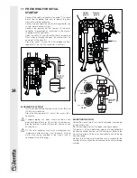
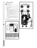
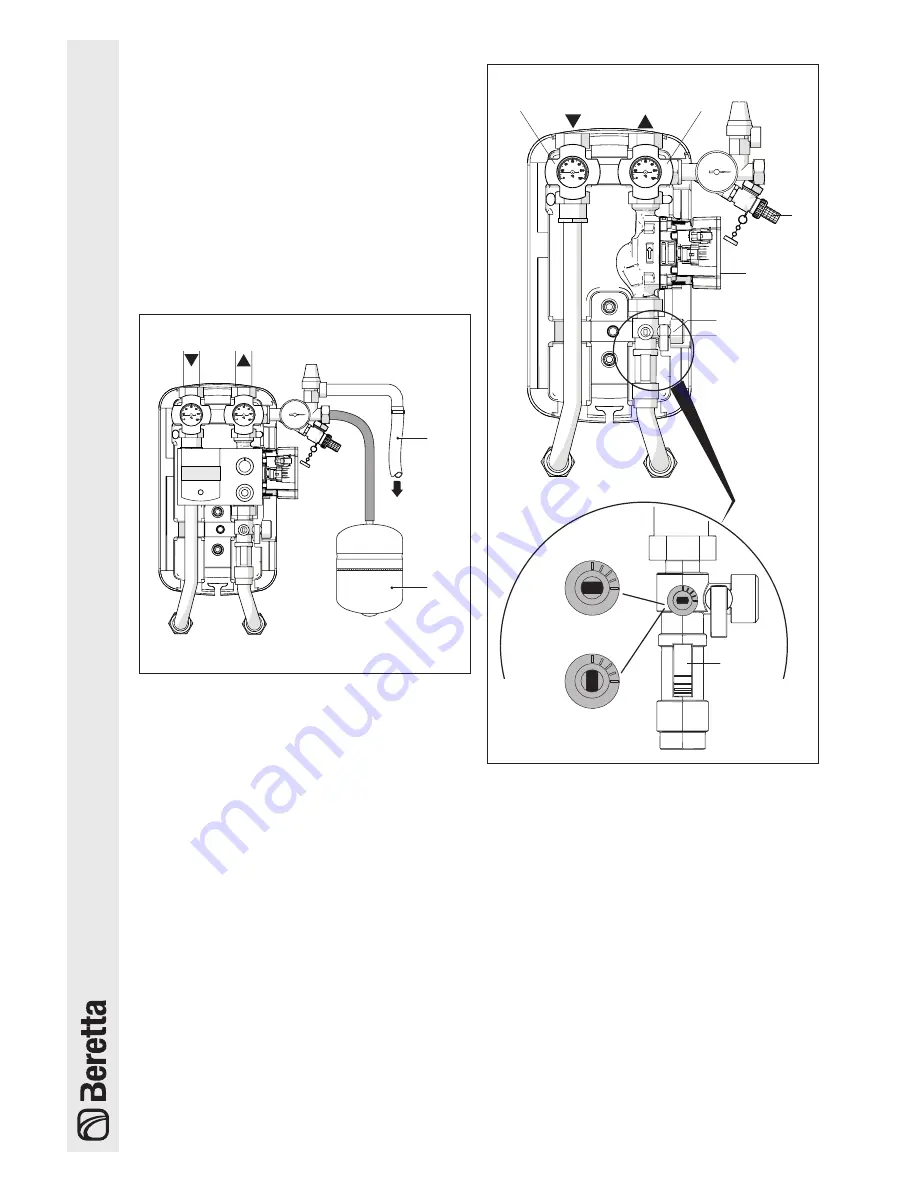
- Connect the safety valve drain to a pipe (T) to avoid
burns from expelled fluid and to permit the heat
transfer fluid to be recovered
- Connect up an expansion vessel (E) designed for use
in solar water heating systems
- Connect the pump and the sensors to the solar
controller (if provided) as instructed in the manual
supplied with the controller.
- Open the cocks (A) and (B) on the return valve group
- Flush water in through the cock (B) and wait for it to
come out of the cock (A)
- Close the cocks (A) and (B) and re-open the flow
regulator (V) (so that the screw slot is vertical).
SAFETY
DRAIN
T
E
FLUSHING THE SYSTEM
- Turn the knobs of the outlet and return valves (M) and
(R) fully anti-clockwise
- Close the flow regulator (V) (so that the screw slot is
horizontal)
b
If copper piping has been used and joints have
been hot brazed, flush out the system to remove any
brazing residues. Seal test the system after you have
flushed it out.
b
Fill the solar collector circuit with water/glycol mix
immediately after flushing it out, because flushing
water may remain trapped in the circuit (with a
consequent risk of freezing).
Return
group
Outlet
group
R
M
Pump
A
B
V
Graduated
scale in
l/min.
Flow
regulator V
position
CLOSED
position
OPEN
ADJUSTING THE FLOW
Correct flow adjustment is essential to proper functioning
of the entire system.
Set the flow regulator (V) fully open (see figure above).
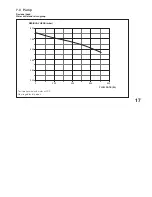
The pump is of the modulating type and is controlled by
the solar controller by means of a PWM signal. Refer to the
manual supplied with the solar controller to set the pump
flow rate range.
Make sure that the pump’s rated flow rate is suitable for the
number of solar collectors connected to the solar storage
cylinder.

