


41
Bentone BG550/650
General
Control box
LMV
X10-05,2
LFL.....
24
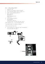
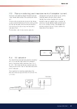
11.3 Flame monitoring and measurement of ionisation current
The burner is monitored according to the ionisation principle.
Check the ionisation current on start-up and on each service
call.
The reason for a low ionisation current may be leaking
currents, bad connection to earth, dirt or a faulty position
of the lame electrode in the burner head. Sometimes
also a faulty gas/air mixture may cause too weak a
ionisation current.
The ionisation current is measured by means of a
microampere meter (µA) connected in series with the
lame electrode and the gas burner control.
Connect the µA-meter, see igure. Min. required
ionisation current according to table. In practice this
current must be considerably higher, preferably more
than 10 µA. All the gas burners are equipped with a
ionisation cable that can be slit which facilitates the
connection of the µA-device.
Gas control
Connection to
terminal in gas
control
Min. ionisation
current required
LFL
24
10 µ A
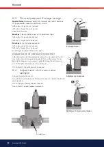
11.4 UV-detector
This should not be exposed to temperatures exceeding
60°C. The current passing through the UV-detector,
when it is being illuminated, should be at least 70 µ A
for LFL1.. This current can be measured by means of a
moving coil instrument. Checks should only be made if a
fault is suspected.
The capacitor, which sould be placed between the
terminals on the moving coil instrument, must be of 100
µ F 10-25 V.
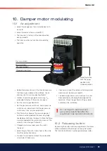
Flame monitoring


