

33
Bentone BG550/650
General
2
4
5
6
7
8
9
10
11
12
13
14
17
16
15
18
18
18
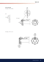
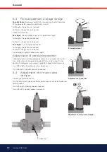
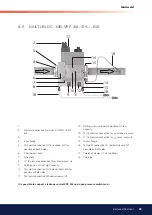
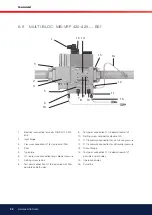
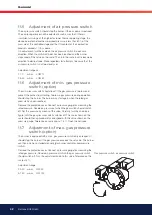
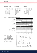
8.5
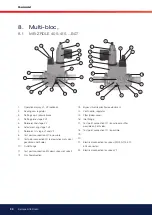
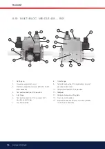
MULTI-BLOC, MB-VEF 412-415.... B01
1.
2.
Electrical connection for valves DIN EN 175 301-
803
3.
4.
Input lange
5.
Test point connection G 1/8 upstream of ilter,
possible on both sidees.
6.
Filter (below cover)
7.
Type plate
8.
G 1/8 pressure connection for p
L
blower pressure
9.
Setting screw, ratio V, high capacity
10. Test point connection G 1/8 downstream of ilter
possible of both sides
11. Test point connection M4 downstream of V2
12. Setting screw, zero point adjustment N, low
capacity
13. G 1/8 pressure connection for p
F
furnace pressure
14. G 1/8 pressure connection for p
Br
burner pressure
15. Output lange
16. Test point connection G 1/8 downstream of V1,
possible on both sides
17. Operation display V1, V2 (optional)
18. Pulse line
It is possible to connect a leakage control VPS 504 and a gas pressure switch maxi.


