

30
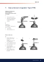
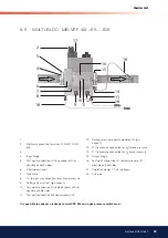
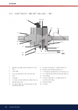
Bentone BG550/650
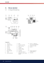
General
1.
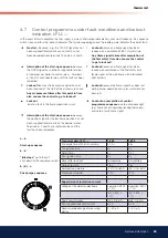
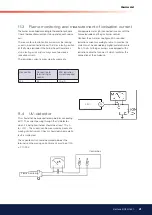
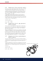
Operation display V1, V2 (optional)
2.
Sealing cap, regulator
3.
Setting cap, hydraulic brake
4.
Setting plate stage 2 V2
5.
Solenoid, 2nd stage V2
6.
Adjustment ring stage 1 V2
7.
Solenoid, 1st stage V1 and V2
8.
Test point connection G 1/8 possible
9.
Test point connection G 1/8 downstream of valve 1,
possible on both sides
10. Outlet lange
11. Test point connection M4 down stream of valve 2
12. Gas low direction
13. Bypass throttle pilot lame adjustment
14. Vent nozzle, regulator
15. Filter (below cover)
16. Inlet lange
17. Test point connection G 1/8 upstream or ilter,
possible on both sides
18. Test point connection G 1/8 possible
19.
20.
21. Electrical connection for valves (DIN EN 175 301-
803 connector).
22. Electrical connection for valves V2
2
1
3
4
5
6
7
8
9
10
11
12
13
14
15
16
17
18
21
22
1
2
3
4
5
6
7
8
9
10
11
12
13
15
17
18
21
16
22
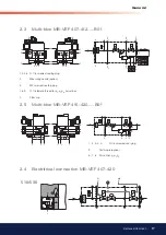
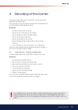
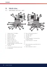
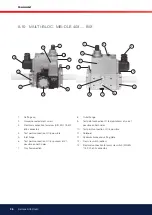
8. Multi-bloc,
8.1
MB-ZRDLE 405-415....B07


