22
GSM/GPRS Alarm Communnicator
OPERATING PRINCIPLES
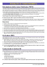
Simulated Land Line
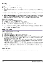
The Simulated land line provides the alarm control panel (with dialer interface) with a backup line in the event of PSTN line trouble. If the
voltage on the land line terminals (
LE
) drops below 3 V for a period of between 10 to 45 seconds (depending on the device connected
to the
LI
terminals), this Device will switch the connected telephone device to the GSM Network for a full 30-40 seconds interval, at the end
of this interval, it will check the land line:
—
if the land line has been restored
, it will switch the connected telehone device back to the land line;
—
if the land line is still down
, it will continue to simulate the land line until it is restored.
This Device will not switch during ongoing calls. The simulated line will provide the line ring voltage for incoming calls and will decode
DTMF dialling
,
,
,
,
,
This Device is unable to decode Pulse dialling.
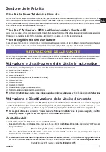
The
Function Priority
(to be selected during the programming phase) will determine how this Device manages communications (SMS
and ContactID) and calls from the telephone device connected to the
LI
terminals (e.g. Control panel).
Sequence
When alarm is triggered, the Alarm Panel goes off-hook.
The Device will assert dial tone.
Control Panel dials the number of the central station. Ensure the alarm panel inserts a minimum 1-second pause, or has dial tone
search enabled before dialing the number.
The Device detects the DTMF dialing and stops dial tone.
The Device will send the required Contact ID dual tone handshake.
After receiving the handshake, panel transmits alarm message in DTMF format.
The Device decodes and transforms DTMF digits into the packet and sends it to the Central Station Receiver over the GPRS network.
The receiver acknowledges the alarm and sends command to the Device to generate the corresponding 1400 hz kiss-off signal for
800ms minimum.
After the Device generates kiss-off, the panel goes on-hook if no more alarms need to be sent, or it can send the next alarm.
SMS function
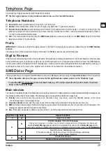
This operating mode allows this Device to send text messages to 8 telephone numbers. The messages can be associated with the following
events:
Alarm signals on the 4 Programmable Input lines: 2 preset messages — Alarm and End of Alarm.
Land Line Test: 2 preset messages — Line down and Line restored.
Power supply Test: 2 preset messages — Trouble and Trouble clear
Periodic message: 1 message to be sent at regular intervals (accepted values 1 through 999999 minutes).
,
,
,
,
,
The SMS messages will be sent to the programmed numbers when the respective events occur.
ContactID Mode
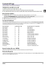
This operating mode will allow this Device to send calls to the Central Station. The events are being generated using four inputs L1 - L4.
Alarm signals: require Event Codes and Customer Account Codes
Status signal, with a Customer Account Code:
– Land Line Test
– Power supply Test
– Call queue full
– Periodic report (to be sent at regular intervals)
,
,
,
,
,
The Contact ID reports will be sent when the respective events occur.
Summary of Contents for BGSM-G
Page 1: ...I I I I I G G G G G BGSM G GSM GPRS Alarm Communicator Comunicatore di Allarme GSM GPRS ...
Page 6: ...6 Comunicatore di Allarme GSM GPRS 5 Fig 2 Esempio di collegamento ...
Page 16: ...16 Comunicatore di Allarme GSM GPRS ...
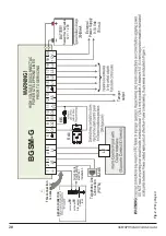
Page 20: ...20 GSM GPRS Alarm Communnicator Fig 2 Wiring Diagram 5 0 ...
Page 30: ......
Page 31: ......

