background image

17

D

11/ 2019 

BENNING CM 10–PV


Crest-Factor von 2,5 bis 3,0 zusätzlicher 7,0 %

Maximaler Crestfaktor des Messsignals:


Crest-Faktor 3,0 @ 3000 Digit


Crest-Faktor 2,0 @ 4500 Digit


Crest-Faktor 1,5 @ 6000 Digit

Messwerte < 20 Digit werden in der Digitalanzeige 

K

 auf 0 gesetzt.

Rechtecksignale sind nicht spezifiziert.

HFR-Funktion (Tiefpassfilter)

zusätzlicher Fehler für Funktion V

AC

, A

AC 

und 

 (flexibler AC-Stromwandler)

± 4 % zur angegebenen Messgenauigkeit (45-Hz - 200 Hz)

Grenzfrequenz fg (- 3 db): 800 Hz

7.1  Spannungsbereiche (V AC, V DC)

Funktion

Messbereich Auflösung

Messgenauigkeit

V AC

600,0 V

1000 V

0,1 V

1 V

± (1,0 % + 7 Digit), 45 Hz - 400 Hz, Sinus

V DC

600,0 mV

0,1 mV

± (0,7 % +  7 Digit)

600,0 V

1000 V

0,1 V

 1 V

± (0,7 % + 4 Digit)

Überlastschutz:   

1000 V

AC/DC

Eingangswiderstand: DC: 10 MΩ, AC: 10 MΩ II < 100 pF

7.2  Spannungsbereiche (PV) über Messadapter BENNING TA PV

Funktion

Messbereich Auflösung

Messgenauigkeit

PV V DC

600,0 V

2000 V

0,1 V

1 V

± (2,0 % + 7 Digit)

PV V AC

600,0 V

1500 V

0,1 V

1 V

± (2,0 % + 7 Digit), 45 Hz - 400 Hz, Sinus

Überlastschutz:   

1000 V

AC/DC

Eingangswiderstand: DC: 10 MΩ, AC: 10 MΩ II < 100 pF

7.3  Strombereiche (A 

AC/DC

)

Funktion

Messbereich Auflösung

Messgenauigkeit

A AC 

[1] [2]

60,00 A

600,0 A

0,01 A

0,1 A

± 2,0 % + 7 Digit

A DC 

[1]

60,00 A 

600,0 A

0,01 A

0,1 A

± 2,0 % + 7 Digit

[1]

  Messwerte unter < 5 A, zuzüglich 10 Digit

[2]

  Frequenz > 100 Hz, zuzüglich 1 %

Überlastschutz:   

600 A 

AC/DC

Frequenzbereich:   45 Hz - 400 Hz, Sinus

Positionsfehler:   

± 1 % des Messwertes

7.3.1   Mikroampere-Strombereiche (µA 

AC/DC

)

Funktion

Messbereich Auflösung

Messgenauigkeit

µA 

AC/DC

400,0 µA

4000 µA

0,1 µA

1 µA

± 1,0 % + 5 Digit

Überlastschutz:   

1000 V 

AC/DC

Eingangswiderstand: ca. 3 kΩ

Frequenzbereich: 

45 Hz - 400 Hz (Sinus)

7.3.2 

 INRUSH-Funktion (Einschaltstrommessung)

zusätzlicher Fehler für Funktion A

AC

, und 

 (flexibler AC-Stromwandler)

± 3 % zur angegebenen Messgenauigkeit

Integrationszeit:  100 ms

Triggerstrom: 

> 0,5 A

eff

 im 60 A Messbereich, > 5 A

eff

 im 600 A Messbereich

Summary of Contents for 044683

Page 1: ...LOG 2 Sec Inrush Volt Sense 2 Sec 2 Sec 2 Sec HFR MIN MAX CM 10 PV D Bedienungsanleitung Operating manual F Notice d emploi Gebruiksaanwijzing BENNING CM 10 PV...

Page 2: ...sh Volt Sense 2 Sec 2 Sec 2 Sec HFR MIN MAX CM 10 PV D Bedienungsanleitung Operating manual F Notice d emploi Gebruiksaanwijzing BENNING CM 10 PV Mehrsprachige Anleitung unter www benning de Multiling...

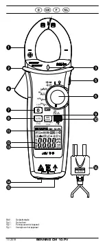
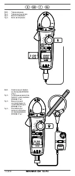
Page 3: ...Volt Sense 2 Sec 2 Sec 2 Sec HFR MIN MAX CM 10 PV TA PV 11 2019 BENNING CM 10 PV 4 K L M N O 6 J 7 9 P 8 2 3 5 Bild 1 Ger tefrontseite Fig 1 Device front Fig 1 Panneau avant de l appareil Fig 1 Voorzi...

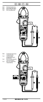
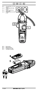
Page 4: ...ING CM 10 PV Bild 2 Gleichspannungsmessung Fig 2 Direct voltage measurement Fig 2 Mesure de tension continue Fig 2 Meten van gelijkspanning Bild 3 Wechselspannungsmessung Frequenzmessung Fig 3 Alterna...

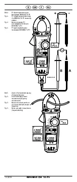
Page 5: ...A PV Fig 4 PV voltage measurement using the BENNING TA PV measuring adapter Fig 4 Mesure de tension PV avec adaptateur de mesure BENNING TA PV Fig 4 PV spanningsmeting met meetadapter BENNING TA PV Bi...

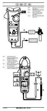
Page 6: ...g Fig 7 Resistance measurement continuity and diode testing capacity measurement Fig 7 Mesure de r sistance contr le de continuit et de diodes mesure de capacit Fig 7 Weerstandsmeting doorgangs diodet...

Page 7: ...Stromwandler BENNING CFlex 1 Fig 9 Current measurement with the flexible AC current transformer BENNING CFlex 1 Fig 9 Mesure de courant avec transformateur de courant alternatif souple BENNING CFlex...

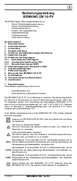
Page 8: ...ld 11 Batteriewechsel Fig 11 Battery replacement Fig 11 Remplacement de la pile Fig 11 Vervanging van de batterij Bild 10 Spannungsindikator mit Summer und LED Fig 10 Voltage indicator with buzzer and...

Page 9: ...rwendung des Messadapters BENNING TA PV erh ht sich der Nennspannungsbereich auf 1500 V AC 2000 V DC N heres hierzu im Abschnitt 6 Umgebungsbedingungen und Abschnitt 8 2 2 Span nungsmessung Schaltstel...

Page 10: ...BENNING CM 10 PV darf nur in Stromkreisen der ber spannungskategorie III mit max 1000 V Leiter gegen Erde oder berspannungskategorie IV mit max 600 V Leiter gegen Erde benutzt werden Hierzu sind geei...

Page 11: ...Tuch und Reinigungsmittel trocken abwischen Kein Poliermittel oder L sungsmittel verwenden 3 Lieferumfang Zum Lieferumfang des BENNING CM 10 PV geh ren 3 1 ein St ck BENNING CM 10 PV 3 2 zwei St ck S...

Page 12: ...uchsendefinition mit angezeigt 5 1 3 Die Bereichs berschreitung wird mit 0L oder 0L angezeigt Achtung keine Anzeige und Warnung bei berlast Ein berschreiten von gef hrlichen Ber hrungsspannungen 60 V...

Page 13: ...en initiiert Der ber diesen Zeitbereich gemittelte Wert wird dann angezeigt Durch l ngeren Tastendruck 2 s der Taste 8 wird in den Messmodus zur ckgeschaltet Triggerstrom 0 5 A im 60 A Messbereich 5 A...
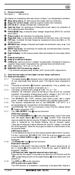
Page 14: ...a 200 Stun den ohne Hintergrundbeleuchtung und Bluetooth 5 1 18 Ger teabmessungen L x B x H 240 x 86 x 48 mm Ger tegewicht 445 g mit Batterien 5 1 19 Gr te Zangen ffnung 37 mm 5 1 20 Die mitgelieferte...

Page 15: ...Jeder Start des Datenloggers LOG l scht den internen Speicher und somit alle gespeicherten Messwerte LOG 2 Sec Press Press Press 2 Sec Press 2 Sec LOG 2 Sec Wait 2 Sec 5 2 3 Manuelle Speicherung SAVE...

Page 16: ...1 IEC EN 60529 3 erste Kennziffer Schutz gegen Zugang zu gef hrlichen Teilen und Schutz gegen feste Fremdk rper 2 5 mm Durchmesser 0 zweite Kennziffer Kein Wasserschutz Arbeitstemperatur und relative...

Page 17: ...Funktion Messbereich Aufl sung Messgenauigkeit PV V DC 600 0 V 2000 V 0 1 V 1 V 2 0 7 Digit PV V AC 600 0 V 1500 V 0 1 V 1 V 2 0 7 Digit 45 Hz 400 Hz Sinus berlastschutz 1000 VAC DC Eingangswiderstand...
Page 18: ...t anlegen Messbereich Aufl sung Messgenauigkeit 100 0 F 0 1 F 1 9 4 Digit 1000 F 1 F berlastschutz 1000 VAC DC 7 6 Frequenzbereiche Hz Messbereich Aufl sung Messgenauigkeit 100 00 Hz 0 01 Hz 0 3 5 Dig...
Page 19: ...tential beachten berspannungskategorie des Stromkreises beachten Montie ren Sie die Aufsteckkappen CAT II IV auf die Kontaktspitzen vor Messungen in Stromkreisen der berspannungskategorie CAT III oder...

Page 20: ...eiter mittig mit der Zange 1 umfassen In der Funktion kann ber die MODE Taste blau J die Umschaltung auf Frequenzmessung Hz vorgenommen werden Messwert an der Digitalanzeige K ablesen siehe Bild 5 Gle...

Page 21: ...eren Die Sicherheitsmessleitungen mit den Messpunkten kontaktieren und den Messwert an der Digitalanzeige K ablesen F r eine normale in Flussrichtung angelegte Si Diode wird die Flussspan nung zwische...

Page 22: ...lanzeige K blinkt Mit der MIN MAX Taste 9 die Umschaltung auf Hi hohe Empfindlich keit bzw Lo niedrige Empfindlichkeit vornehmen Die rote Sicherheitsmessleitung mit dem Messpunkt Anlagenteil kontaktie...

Page 23: ...ng Benning garantiert die Einhaltung der in der Bedienungsanleitung aufgef hrten technischen Spezifikationen und Genauigkeitsangaben f r das erste Jahr nach dem Auslieferungsdatum Um die angegebenen G...

Page 24: ...24 D 11 2019 BENNING CM 10 PV 11 Umweltschutz Bitte f hren Sie das Ger t am Ende seiner Lebensdauer den zur Verf gung ste hen den R ckgabe und Sammelsystemen zu...

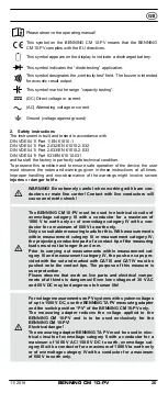
Page 25: ...TA PV measuring adapter the nominal voltage range increases to 1500 V AC 2000 V DC see section 6 Am bient conditions and section 8 2 2 Voltage measurement switch position PV for details The following...

Page 26: ...ts of overvoltage category III with a conductor for a maximum of 1000 V to earth only or of overvoltage category IV with a con ductor for a maximum of 600 V to earth only Only use suitable measuring l...

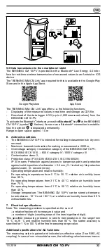
Page 27: ...h and clean ing agent Do not use any polishing agents or solvents 3 Scope of delivery The scope of delivery of the BENNING CM 10 PV comprises 3 1 One BENNING CM 10 PV 3 2 Two safety measuring lead red...

Page 28: ...efinition is indicated as 5 1 3 The range overload will be displayed with OL or OL Attention No indication and prior warning in the event of an overload condition A exceeding of dangerous contact volt...

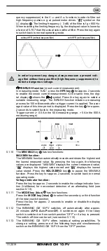
Page 29: ...in the 600 A measuring range engine off trigger point engine on time 5 1 10 The MIN MAX key 9 has two functions MAX MIN function The MIN MAX function automatically records and stores the highest and t...

Page 30: ...kaline battery 5 1 18 Dimensions of the BENNING CM 10 PV L x W x H 240 x 86 x 48 mm Weight 445 g with batteries 5 1 19 Current clamp opening 37 mm 5 1 20 The safety measuring leads supplied are expres...

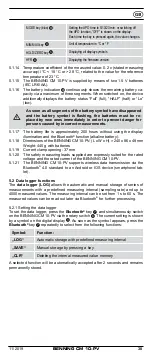
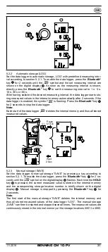
Page 31: ...ach start of the data logger LOG deletes the internal memory and thus all stored measured values LOG 2 Sec Press Press Press 2 Sec Press 2 Sec LOG 2 Sec Wait 2 Sec 5 2 3 Manual storage SAVE Set the da...

Page 32: ...1000 V category III Contamination class 2 Protection class IP 30 DIN VDE 0470 1 IEC EN 60529 IP 30 means Protection against access to dangerous parts and protection against solid impurities of a diam...

Page 33: ...600 0 mV 0 1 mV 0 7 7 digits 600 0 V 1000 V 0 1 V 1 V 0 7 4 digits Overload protection 1000 VAC DC Input resistance DC 10 M AC 10 M II 100 pF 7 2 Voltage ranges PV via BENNING TA PV measuring adapter...

Page 34: ...n resistance is less than 20 to 200 Response time 100 ms Acoustic indication 2 7 kHz 7 5 Capacity ranges F Conditions Capacitors discharged and connected in accordance with the pola rity stated Measur...

Page 35: ...c Do not exceed the maximum permitted voltage with respect to earth potential Please observe the overvoltage category of the electric circuit Attach the protective caps CAT III IV to the contact tips...

Page 36: ...e on BENNING CM 10 PV Press the ZERO button 5 2s to set the BENNING CM 10 PV to the start ing point only DC coupling mode Operate opening lever 4 clamp 1 single wire live conductor centrally by means...

Page 37: ...black safety measuring lead to the COM jack N of the BENNING CM 10 PV Connect the red safety measuring lead to the jack O of the BENNING CM 10 PV Press the MODE key blue J 3 times to enable the diode...

Page 38: ...measuring lead to the jack O of the BENNING CM 10 PV Use the rotary switch 6 to select the required function on BENNING CM 10 PV Press and hold the MIN MAX key 9 for 2 seconds to enable the voltage in...

Page 39: ...mental protection Do not dispose of discharged batteries via the household waste In stead return them to a collecting point for discharged batteries or spezial waste Please look for information in you...

Page 40: ...10 PV Insert the bent terminals into the testing or measuring device 11 Environmental note At the end of product life dispose of the unserviceable device via appro priate collecting facilities provid...

Page 41: ...000 V AC DC En utilisant l adaptateur de mesure BENNING TA PV la plage de tension nominale passe 1500 V AC 2000 V DC voir aussi le paragraphe 6 Conditions d envi ronnement et paragraphe 8 2 2 Mesure d...

Page 42: ...ectriques de la cat gorie de surtension III avec des conducteurs de 1000 V max par rapport la terre ou de la ca t gorie de surtension IV avec des conducteurs de 600 V max par rapport la terre Utiliser...

Page 43: ...ent avec un chiffon sec et un d tergent N utilisez jamais des produits de polissage ou des solvants 3 Contenu de l emballage Les composants suivants sont inclus dans le contenu de l emballage du BENNI...

Page 44: ...ales 5 1 1 L affichage num rique K est un affichage cristaux liquides de 4 carac t res de 15 mm de hauteur avec point d cimal La valeur maximale affi ch e est 6000 5 1 2 L affichage de polarit L est a...

Page 45: ...d marrage Au mode de mesure A AC la mesure du courant de d marrage est activ e en appuyant sur la touche HFR 8 pour 2 secondes envi ron En m me temps le symbole est affich sur l cran num rique K Appu...

Page 46: ...ors de la mise en marche de l appareil c D s que tous les segments du symbole de pile sont teints et le symbole de pile clignote il faut remplacer les piles imm diatement afin d viter des risques aux...

Page 47: ...7 pendant 2 secondes Remarque Chaque d marrage de l enregistreur de donn es LOG efface la m moire in terne et donc toutes les valeurs mesur es enregistr es LOG 2 Sec Press Press Press 2 Sec Press 2 S...

Page 48: ...rtension cat gorie d installation de l appareil BENNING CM 10 PV CIE 60664 CIE 61010 600 V cat gorie IV 1000 V cat gorie III Degr d encrassement 2 EN 61010 1 Type de protection IP 30 DIN VDE 0470 1 CI...

Page 49: ...e sp cifi e 45 Hz 200 Hz Fr quence limite fg 3 dB 800 Hz 7 1 Plages de tension V AC V DC Fonction Domaine de mesure R solution Pr cision de mesure V AC 600 0 V 1000 V 0 1 V 1 V 1 0 7 chiffres 45 Hz 40...

Page 50: ...0 k 0 1 k Continuit 600 0 0 1 0 9 7 chiffres Diode 1 500 V 0 001 V 0 9 4 chiffres Avant la mesure un ventuel d calage doit tre d termin en court circui tant les c bles de mesure et en les soustrayant...

Page 51: ...correspondent ceux du BENNING CM 10 PV Contr lez l isolation des c bles de mesure de s curit En cas de d t riora tion de l isolation il faudra remplacer imm diatement les c bles de mesure de s curit C...

Page 52: ...est mis et le symbole Prob est affich sur l cran num rique K Un signal acoustique est mis si le mauvais mode de couplage par exemple AC au lieu de DC est s lectionn dans la plage de mesure PV et une t...

Page 53: ...est inf rieure une valeur entre 20 et 200 le ronfleur int gr de l appareil BENNING CM 10 PV met un signal acoustique et la LED rouge 3 s allume voir figure 7 Mesure de r sistance contr le de continuit...

Page 54: ...que K voir figure 9 Mesure de courant avec transformateur de courant alternatif souple BENNING CFlex 1 8 10 Indicateur de tension c La fonction de l indicateur de tension ne sert pas d terminer l abse...

Page 55: ...d connecter imm diatement le BENNING CM 10 PV l enlever du circuit mesurer et emp cher qu il ne puisse tre r utilis 9 2 Nettoyage Nettoyer l ext rieur du bo tier avec un chiffon propre et sec except...

Page 56: ...mesure c bles de mesure de s curit r f rence 044145 avec capuchon 1000 V CAT III 600 V CAT IV sans capuchon 1000 V CAT II calibre courant maximum 10 A adaptateur de mesure BENNING TA PV r f 10217846...

Page 57: ...2000 VDC zie ook pt 6 Gebruiksomstandigheden en pt 8 2 2 Spanningsmeting PV stand In de gebruiksaanwijzing en op de BENNING CM 10 PV worden de volgende symbolen gebruikt Aanleggen om GEVAARLIJKE ACTI...

Page 58: ...e of overspanningscategorie IV met max 600 V ten opzichte van aarde Gebruik alleen passende meetsnoeren voor deze Bij metingen binnen de meetcategorie III of de meetcategorie IV mag het uit stekende g...

Page 59: ...bruik geen schuurof oplosmiddelen 3 Leveringsomvang Bij de levering van de BENNING CM 10 PV behoren 3 1 E n BENNING CM 10 PV 3 2 Twee veiligheidsmeetsnoer rood zwart L 1 4 m art nr 044145 3 3 Twee vei...

Page 60: ...f waarschuwing bij overbelasting Een overschrij ding van gevaarlijke contactspanning 60 V DC 30 V AC rms wordt aangegeven door een extra knipperend symbool 5 1 4 Bij de BENNING CM 10 PV weerklinkt er...

Page 61: ...r uit Trigger punt Motor aan tijd 5 1 10 De MIN MAX toets 9 heeft twee functies MAX MIN functie De MIN MAX functie registreert en bewaart automatisch de hoogste en laagste meetwaarde Bij een nieuwe dr...

Page 62: ...het apparaat L x B x H 240 x 86 x 48 mm Gewicht 445 gram met batterijen 5 1 19 Opening van de stroomtang 37 mm 5 1 20 De meegeleverde veiligheidsmeetsnoeren zijn zonder meer geschikt voor de BENNING...

Page 63: ...LOG datalogger worden het interne geheugen en dus ook alle opgeslagen meetwaarden gewist LOG 2 Sec Press Press Press 2 Sec Press 2 Sec LOG 2 Sec Wait 2 Sec 5 2 3 Manuele opslag SAVE Stel de datalogge...

Page 64: ...61010 600 V categorie IV 1000 V categorie III Beschermingsgraad stofindringing 2 EN 61010 1 Beschermingsgraad IP 30 DIN VDE 0470 1 IEC EN 60529 Betekenis IP 30 Het eerste cijfer 3 Bescherming tegen b...

Page 65: ...z sinus V DC 600 0 mV 0 1 mV 0 7 7 digits 600 0 V 1000 V 0 1 V 1 V 0 7 4 digits Beveiliging tegen overbelasting 1000 VAC DC Ingangsweerstand DC 10 M AC 10 M II 100 pF 7 2 Spanningsbereik PV met de mee...

Page 66: ...7 kHz 7 5 Capaciteitsbereik F Voorwaarde condensatoren ontladen en de meetpennen over nkomstig de polariteit aanleggen Meetbereik Resolutie Nauwkeurigheid 100 0 F 0 1 F 1 9 4 digits 1000 F 1 F Beveil...

Page 67: ...nteer de opsteekdoppen CAT III IV op de contactpunten voor metingen in circuits binnen de overspanningscategorie CAT III of IV Gevaarlijke spanning De hoogste spanning die aan het COM bus N bus O van...

Page 68: ...tie omgeschakeld worden op de frequentiemeting Hz Lees de gemeten waarde af in het display K zie fig 5 meten van gelijk wisselstroom frequentiemeting 8 3 1 Meten van microampere gelijk wisselstroom st...

Page 69: ...Si diode wordt een stroomspanning van 0 400 V tot 0 800 V aangegeven De aanduiding 000 wijst op een kortsluiting in de diode F r eine normale in Flussrichtung angelegte Si Diode wird die Flussspan nu...

Page 70: ...en wacht tot het symbool op de display K verschijnt Met de MIN MAX toets 9 kunt u kiezen tussen Hi hoge gevoelig heid en Lo lage gevoeligheid Breng de rode veiligheidsmeetleiding in contact met het m...

Page 71: ...rborgt de naleving van de in de gebruiksaanwijzing vermelde technische gegevens en nauwkeurigheidsinformatie gedurende het 1ste jaar na de leveringsdatum Op de nauwkeurigheid van de metingen te waarbo...

Page 72: ...Benning Elektrotechnik Elektronik GmbH Co KG M nsterstra e 135 137 D 46397 Bocholt Phone 49 0 2871 93 0 Fax 49 0 2871 93 429 www benning de E Mail duspol benning de...

Reviews: