36
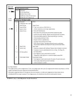
FIGURE 42 - 4S-2M Side Control and Axle Control Electrical Connections
ECU
X1-CODING A (GREY)
X2-CODING B (BLACK)
CMN
CMN
B
HLD
1
2
3
4
5
6
12
11
10
9
8
7
B
A
HLD
A
GND
ECU
V
ECU
WL
REL
T-
REL
B
A
WL
T+
DIAG
V
BL
V
DIA
2
11
1587
+
GND
1
12
DIA
1587
-
SS
3
10
A-
SS
D+
4
9
SS
A+
SS
D-
5
8
SS
B-
SS
C+
6
7
SS
B+
SS
C-
Top–Looking into Harness
White (Ground)
Blue (Switched 12V
Constant Power From
Tractor)
ECU Side
Wheel Side
+
Harness Side
Warning
Light Side
A–SAE J1587+
B–SAE J1587–
C–+12 Volts
D–Not Used
E–Ground
F–Not Used
B
C
D
E
F
A
Front
Looking Into Valve
Release
Hold
Common
No
Connection
1
3
2
Red
(Brake Light Power)
Road Side
Top View
Power
Cable
ECU Side
Trailer
Side
A–Brake Light
B–Perm. Power
C–Not Used
D–Warning Lamp
E–Ground
E
C
D
A
B


