background image

20

Front

3/8" O. D. Nylon Tubing

3/8" O. D. Nylon Tubing (Alt. 1/2" O. D.)

3/8" I. D. Hose

Key

4S-2M Side Control Air System Configuration (Top View)

Gladhand

Gladhand

TEV or STEV

Spring Brake Control

Res.

Res.

Emergency Brake Chamber

Service Brake Chamber

ABS

ECU

Relay Valve A

Relay

Valve

B

Supply Line

Service (Control) Line

Road Side

Top View

Road Side

Top View

Power Cable

4S-2M Side Control Electrical Configuration (Top View)

J560 Connector

Trailer

Side

ABS Warning Lamp

ECU

Relay

Valve A

Stand
Alone
Relay

Valve B

Diagnostic Port

Speed Sensor

Sensor D

Sensor C

Sensor A

Sensor B

Front

ABS

ECU Side

Description

Quantity

ECU/Relay Valve

1

Stand Alone Relay Valve

1

Sensor/Diagnostic Cable

1

Valve/Power Cable

1

Sensors — 0.4m Cable

4

Sensor Friction Sleeve

4

Parts List

Wheel Sensor

ECU

Side

Wheel

Side

Warning

Light Side

Harness Side

Warning Lamp Connector

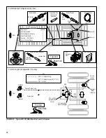
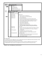
FIGURE 25 - Typical 4S-2M Side Control ABS Electrical and Air System (Top View)

Summary of Contents for A-18 TRAILER ABS

Page 1: ...pending wheel lock Maintain optimum wheel slip Maximize overall braking effectiveness Minimize tendencies for trailer swing out during hard braking conditions Document Revision Level This document is subject to revision For updates please visit www bendix com Bendix A 18 Trailer ABS Gen 4 and Gen 5 ABS FIGURE 1 ABS Controller Assemblies Table of Contents Power Requirements for ABS 3 General Air Br...

Page 2: ... at which time the warning lamp will activate A new TMC RP Recommended Practice is being developed which recommends that trailer manufacturers provide a 1 0 volt safety margin over the 8 5 volt minimum System current requirements will not exceed 0 5 amps per control unit and three amps per valve A 18 trailer ABS system modulators have a nominal resistance of 5 5 ohms and require approximately two ...

Page 3: ...r a typical two axle trailer the minimum required volume is therefore 2848 CID Reservoir size requirements for non ABS and ABS equipped systems are the same Air Consumption DuringABS activation there is a loss of reservoir pressure There are no specific requirements limiting air consumption in the U S In Europe Regulation R13 states specific limitations ABS manufacturers take air consumption into ...

Page 4: ...ity The advantage of spring brake priority is that the parking brakes spring brake can be released quickly to permit moving the trailer at start up However spring brake priority systems have failure modes under which the parking brakes can be released and the vehicle operated without functional service brakes Service Brake Priority The advantage of the service brake priority system is that it assu...

Page 5: ... During an ABS release supply air is held off while the chambers are vented to the atmosphere In hold mode supply air is blocked and chamber air is held constant When required air is applied to the chamber at a controlled rate by modulating the hold side of the valve The antilock system does not apply additional braking power Rather it controls air pressure to release and hold brake torque thereby...

Page 6: ...lication Recommendations Refer to the chart on page 8 to determine a recommended ABS installation for your application Basic System 2S 1M The basic system includes two speed sensors and one modulator valve for direct control of one axle and indirect control of an additional axle Other features of the basic system include one ECU connector and a single pin diagnostic lead Standard System 2S 1M 2S 2...

Page 7: ...olly System Application Chart 1 1 1 1 1 1 1 1 1 1 2 2 2 2 1 1 1 1 1 1 1 1 1 1 2 1 1 1 or or or 2 or 2 or 2 1 2 or or and 1 2 and 2 or 1 or 2 or 1 or or or or or or or 2S 1M 2S 2M 4S 2M Axle Control 4S 2M Side Control Trailer Type FIGURE 5 System Application Chart ...

Page 8: ...ted on the driver instrument panel also warns the driver of ABS malfunctions It is not capable of blinking diagnostic fault codes Wheel End Speed Sensor and Tone Wheel Single point variable reluctance magnetic sensor that generates an alternating current signal in response to the movement of teeth on a tone wheel The signal is interpreted by the ECU to monitor wheel speed Diagnostic Port Connector...

Page 9: ...9 FIGURE 6 ABS Trailer Components ...

Page 10: ...tion Identification information for the ECU is located on the connector pinout label refer to Figure 7 The label is located under the ECU cover Refer to the label for the Part Number Serial Number Date Code Depending on configuration the A 18 trailer ABS system ECUs may be equipped with either one connector basic system or two connectors standard system Refer to Figure 8 Bendix Part Number Basic S...

Page 11: ...5 Sensor A Sensor B Sensor C Sensor D X2 6 X2 4 X2 8 Valve A Valve B X2 10 X1 7 X2 2 X2 1 Standard Trailer ECU 2 Connectors X2 3 X2 5 X2 7 X2 9 X1 6 X1 4 X1 3 Hold Common X1 2 X1 1 Common Hold Release Outputs Trailer Mounted Warning Light Diagnostic Plug X1 10 X1 8 X1 9 Inputs Brake Light Power Full Time Power X1 5 Sensor A Sensor B X1 12 X1 1 Valve A X1 7 Basic Trailer ECU 1 Connector X1 2 X1 11 ...

Page 12: ... Do not use thread tape Contamination by thread tape can cause component failure Tighten pipe nipples as follows With Thread Sealant Finger tight plus 1 1 2 turns Without Thread Sealant Finger tight plus 2 turns Clamping A fixture may be necessary to hold the relay valve when reorienting ports or when attaching fittings If a vise is used there is a potential danger of distorting the barrel and pis...

Page 13: ... Do not attempt repairs requiring machining or welding unless specifically stated and approved by the vehicle and component manufacturer 10 Prior to returning the vehicle to service make certain all components and systems are restored to their proper operating condition Relay Valve Operation Modes 1 Apply Treadle pressure is applied to the top of the piston The sleeve is depressed until the outlet...

Page 14: ...nector 6 Install the trailer mounted ABS Warning Lamp 7 Perform the End of Line Checkout Install the Wheel Speed Sensors and Sensor Friction Sleeves Refer to the appropriate diagram for your system and locate the wheel speed sensors Refer to Figures 23 26 1 Install the sensor friction sleeve with the flange stops towards the inboard side of the vehicle 2 Apply high temperature silicon based grease...

Page 15: ...can cause component failure Tighten pipe nipples as follows With Thread Sealant Finger tight plus 1 1 2 turns Without Thread Sealant Finger tight plus 2 turns Leak and Performance Test 1 Park vehicle on level surface and block wheels 2 Make and hold brake application No audible air leaks are permitted 3 Release parking brake and fully charge the air system governor cut out point 4 Turn engine OFF ...

Page 16: ...ness 1 Remove power from the trailer 2 Unlock the ECU cover and remove 3 Install the ECU connectors as follows Standard Plug the grey harness connector into the ECU connector labeled X1 The connector is keyed and can only fit in one direction Plug the black harness connector into the ECU connector labeled X2 This connector is also keyed Basic Plug the green harness connector into the ECU connector...

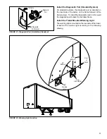
Page 17: ... Diagnostic Port Standard System On standard systems the diagnostic port is installed on the road side of the trailer on the frame forward of the trailer axle s To install the diagnostics port bolt or weld the diagnostic port bracket to the trailer frame Install the Trailer Mounted Warning Light The warning light is mounted on the road side of the trailer forward of the marker light according to t...

Page 18: ...e Wheel Side Power Cable 2S 1M Electrical Configuration Top View J560 Connector Trailer Side Warning Light Side Harness Side ECU Side Warning Lamp Connector ABS Warning Lamp ECU Modulator Valve Diagnostic Port Wheel Sensor Speed Sensor Sensor B Sensor A Front ABS 2S 1M Air System Configuration Top View Shown with Extension Description Quantity ECU Relay Valve 1 Sensor Diagnostics Cable 1 Valve Pow...

Page 19: ...Configuration Top View J560 Connector Trailer Side ABS Warning Lamp ECU Relay Valve A Diagnostic Port Wheel Sensor Speed Sensor Sensor B Sensor A Front ABS Stand Alone Relay Valve B ECU Side Wheel Side Warning Light Side Harness Side Warning Lamp Connector ECU Side Road Side Top View Road Side Top View Description Quantity ECU Relay Valve 1 Stand Alone Relay Valve 1 Sensor Diagnostic Cable 1 Valve...

Page 20: ... 4S 2M Side Control Electrical Configuration Top View J560 Connector Trailer Side ABS Warning Lamp ECU Relay Valve A Stand Alone Relay Valve B Diagnostic Port Speed Sensor Sensor D Sensor C Sensor A Sensor B Front ABS ECU Side Description Quantity ECU Relay Valve 1 Stand Alone Relay Valve 1 Sensor Diagnostic Cable 1 Valve Power Cable 1 Sensors 0 4m Cable 4 Sensor Friction Sleeve 4 Parts List Wheel...

Page 21: ...uration Top View J560 Connector Trailer Side ABS Warning Lamp ECU Relay Valve A Stand Alone Relay Valve B Diagnostic Port Speed Sensor Sensor B Sensor A Sensor C Lift Axle Gen 4 Only Sensor D Front ABS ECU Side Road Side Top View Top View Description Quantity ECU Relay Valve 1 Stand Alone Relay Valve 1 Sensor Diagnostic Cable 1 Valve Power Cable 1 Sensors 0 4m Cable 4 Sensor Friction Sleeve 4 Part...

Page 22: ...tery charger as a power source 2 Remove the weather cap from the trailer diagnostic port 3 Connect either a hand held tester with a Bendix Diagnostic Card or a PC Based Diagnostic system with ServiceRanger s End of Line Software Package to the trailer diagnostic port 4 Follow the appropriate menu selections to verify a That the sensors and valves are connected in their proper locations b That the ...

Page 23: ...PSI Scan Tool Diagnostic Port Deutsch Pin Deutsch 114017 Deutsch HD10 6 12P 0460 204 12141 Warning Light Power Cable Packard Socket Packard Seal Packard 12010300 Packard ECU Side 12124580 12015323 12034342 12010293 Power Cable Packard Pin Packard Seal Packard 12010300 Packard Trailer Harness Side 12124582 12015323 12065158 12010293 ABS N A N A N A N A N A N A N A N A N A N A N A N A N A N A N A N ...

Page 24: ... J1587 data link wiring Reconfigure ECU Recheck fault codes after clearing If warning light remains lit or 17 12 fault code is set drive vehicle to clear and turn off warning light Use Service Ranger diagnostic software standard ECU only Cycle ignition key OFF to ON Activate blink codes with jumper method Check power circuit for ECU Reconfigure ECU YES NO Warning light blinking when activated with...

Page 25: ...ect system problems Hand Held Tester The hand held tester employs menu driven tests for reading ABS fault codes See the documentation provided with the tool for more information An MPSI hand held tester with Bendix proprietary cartridge can be used to read and clear error codes and obtain a short description of failures The tester can initiate valve test sequences and can also read system paramete...

Page 26: ...ector Deutsch HD 10 Connector Serial Communication Interface Laptop PC ServiceRanger Software CD ServiceRanger PC Software ServiceRanger PC software can be used to read and clear error codes and obtain a short description of failures The software can initiate test sequences for controller outputs and can also read system data such as voltage at the ECU wheel speeds and cutout speeds CAUTION Servic...

Page 27: ...n 3 3 8 Ohms No Connection Common Hold Release 1 3 2 FIGURE 31 ABS Valve Pin Identification X2 Black Coding B 12 1 11 2 10 3 9 4 8 5 7 6 X1 Grey Coding A 12 1 11 2 10 3 9 4 8 5 7 6 X1 Green Coding C 12 1 11 2 10 3 9 4 8 5 7 6 BASIC Harness Connector Pin Circuit Description X1 Green Coding C 3 Valve A Com X1 Green Coding C 4 Valve A Hold X1 Green Coding C 10 Valve A Rel STANDARD Harness Connector P...

Page 28: ... listed below to locate and correct sensor related ABS diagnostic trouble codes 1 Access active diagnostic trouble code s using the blink code procedure the hand held tester or ServiceRanger software 2 Look up the code description the possible causes and the repair procedures provided in this section 3 Perform the recommended repair procedures 4 After the repairs are completed clear all codes and ...

Page 29: ...trol configuration with a fault on Sensor B On Gen 5 ABS systems both the configuration codes and the fault codes are reported separately as two part blink codes There are different procedures for retrieving configuration and fault codes Refer to the retrieving codes section of this manual Example A blink code of one flash a pause then one more flash 1 1 indicates a 2S 1M system configuration when...

Page 30: ...and one one thousand two This will allow more accurate fault code retrieval and reduce the possibility of misreading blink code information Before attempting any repairs first retrieve the fault codes and write them down Next clear the fault codes Then once again retrieve the fault codes Only active codes will now be displayed Retrieving Fault Codes Live Feed Gen 5 ABS PLC Capable ECUs 1 Turn igni...

Page 31: ...31 FIGURE 37 Gen 4 ABS Diagnostic Trouble Code Chart Check sensor resistance 1500 2500 ohms ...

Page 32: ...noid to voltage Short circuit from the release solenoid to ground Open circuit at the release solenoid Open circuit on the common line to the valve Short circuit from the hold solenoid to voltage Short circuit from the hold solenoid to ground Open circuit at the hold solenoid System configuration is incorrect Short circuit from the release solenoid to voltage Short circuit from the release solenoi...

Page 33: ...CODING B BLACK CMN CMN B HLD 1 2 3 4 5 6 12 11 10 9 8 7 B A HLD A GND ECU V ECU WL REL T REL B A WL T DIAG V BL VDIA 2 11 1587 GND 1 12 DIA 1587 SS 3 10 A SS D 4 9 SS A SS D 5 8 SS B SS C 6 7 SS B SS C Top Looking into Harness Connector STANDARD SYSTEM ECU Connector Cable Guides Alignment Tabs ECU Cover Alignment Tabs Cover Lock Ref Description Ref Description SSA SSA CMNA HLDA GNDECU VECU Pin Pin...

Page 34: ... Harness Side Warning Light Side ECU Side Wheel Side Front Road Side Looking Into Valve Release Hold Common No Connection 1 2 3 SSA 2 11 SS B SS 1 12 A SS B CMN 3 10 A REL A 4 9 HLDA DIAG 5 8 GND ECU WL T 6 7 V ECU V BL Top View Diagnostic Port Shown with Extension Power Cable ECU Side Trailer Side A Brake Light B Perm Power C Not Used D Warning Lamp E Ground E C D A B ...

Page 35: ... Tractor Harness Side Warning Light Side A SAE J1587 B SAE J1587 C 12 Volts D Not Used E Ground F Not Used B C D E F A ECU Side Wheel Side Front Looking Into Valve Release Hold Common No Connection 1 2 3 Red Brake Light Power Road Side Top View CMN CMN B HLD 1 2 3 4 5 6 12 11 10 9 8 7 B A HLD A GND ECU V ECU WL REL T REL B A WL T DIAG V BL Power Cable ECU Side Trailer Side A Brake Light B Perm Pow...

Page 36: ...S A SS D 5 8 SS B SS C 6 7 SS B SS C Top Looking into Harness White Ground Blue Switched 12V Constant Power From Tractor ECU Side Wheel Side Harness Side Warning Light Side A SAE J1587 B SAE J1587 C 12 Volts D Not Used E Ground F Not Used B C D E F A Front Looking Into Valve Release Hold Common No Connection 1 3 2 Red Brake Light Power Road Side Top View Power Cable ECU Side Trailer Side A Brake L...

Page 37: ...37 FIGURE 43 Electrical Schematic ...

Page 38: ... optimum slip a point where retardation and stability are maximized The brake pressure that is best for the wheel in question is directed individually into each brake chamber MIR Modified Independent Regulation Amethod of controlling the opposite sides of a steer axle during ABS operation so that torque steer and stopping distance are minimized Usually control begins at pure select low and moves t...

Page 39: ...39 ...

Page 40: ...40 BW2262 2004 Bendix Commercial Vehicle Systems LLC All rights reserved 5 2004 Printed in U S A ...

Reviews: