15
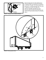
FIGURE 17- Tank Mounted ECU/Relay Valve
ECU
Relay Valve
3/4" Heavy Wall
Steel Pipe Nipple
Reservoir Tank
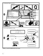
FIGURE 18 - Frame Mounted Relay Valve
ECU
Relay Valve
Frame
Member
Install the ECU/Relay Valve and Stand Alone
Relay Valve
In all installations, the ECU/Relay Valve assembly appears
as Relay Valve “A” in the diagrams. The Stand Alone Relay
Valve is identical to the ECU/Relay Valve except it does
not have the ECU and ECU mounting bracket. The relay
valves may be installed on the reservoirs or a frame
member.
The Stand Alone Relay Valve is the second relay valve in
systems with two relay valves and is labeled Relay Valve
“B” in the diagrams.
Pipe Fitting Torques
Refer to the following torque specifications when installing
pipe nipples. Torques are for NPT threads with thread
sealant applied. Do not use thread tape. Contamination
by thread tape can cause component failure.
Tighten pipe nipples as follows:
•
With Thread Sealant - Finger tight plus 1 1/2 turns
•
Without Thread Sealant - Finger tight plus 2 turns
Leak and Performance Test
1. Park vehicle on level surface and block wheels.
2. Make and hold brake application. No audible air leaks
are permitted.
3. Release parking brake and fully charge the air system
(governor cut out point).
4. Turn engine OFF. Apply the service brake several times,
then hold and check for prompt brake air chamber
application and release at all wheels.
5. Apply brake, then hold. Coat outside of relay valve with
a soap solution. No leakage is permitted.
NOTE: If a sluggish response is noted at all wheels, inspect
for kinked or obstructed air line leading to or from valve.
6. Increase system air pressure to governor cut-off. With
brakes released, coat exhaust port of relay valve with a
soap solution. Leakage of a 1” bubble in 5 seconds is
permissible.
7. Depress foot valve and keep depressed. Coat exhaust
port with a soap solution. Leakage of a 1” bubble in 3
seconds is permissible.


