14
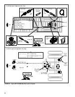
FIGURE 15 - Speed Sensor Installation
Friction Sleeve
Sensor
ABS
Sensor
Bushing
Sensor
Push
FIGURE 16 - Wheel Speed Sensor Components
Installation
Installation of the Bendix
®
A-18
™
trailer ABS system is similar
from one configuration to another. All systems use the same
speed sensors and valves. The differences are in
placement and quantity and the type of ECU, either standard
or basic. Refer to the following general component
instructions and to the wiring and plumbing diagrams for
specific system configuration.
Suggested Order Of Installation
Following is a suggested order of installation of the A-18
™
trailer ABS.
1. Install Wheel Speed Sensors (often part of a dressed
axle).
2. Install Relay Valve(s)/ECU assembly.
3. Install the Power Cable, but do not apply power until
the installation is complete.
4. Route and connect the main ABS Harness.
5. Install the Diagnostic Port Connector.
6. Install the trailer-mounted ABS Warning Lamp.
7. Perform the End-of-Line Checkout.
Install the Wheel Speed Sensors and Sensor
Friction Sleeves
Refer to the appropriate diagram for your system and locate
the wheel speed sensors. Refer to Figures 23-26.
1. Install the sensor friction sleeve with the flange stops
towards the inboard side of the vehicle.
2. Apply high-temperature silicon-based grease to the
body of the speed sensor.
3. Push the speed sensor completely into sensor friction
sleeve by hand until it stops against the tone ring. The
speed sensor is properly installed and adjusted when it
is touching the tone ring. Allowable TIR for the tone
ring is 0.008 inches.
NOTE: The speed sensor must be able to slide freely in
and out of the sensor friction sleeve bore. Operating the
vehicle with seized components will damage the speed
sensor and the tone ring.
4. Route the cable to the frame. Use tie wraps as required
to restrain cable. Use care not to stress sensor cables.
5. Connect sensor cable to harness and install fasteners
to hold the sensor cable in position.


