Technical data
Technical data
iso685-D-B_D00177_05_M_XXEN/07.2017
61
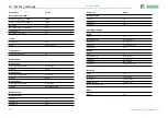
Display
Indication ....................................................................................................................... graphic display 127 x 127 pixels, 40 x 40 mm
2)
Display range measured value.........................................................................................................................................0.1 kΩ…20 MΩ
LEDs
ON (operation LED) ............................................................................................................................................................................green
SERVICE............................................................................................................................................................................................. yellow
ALARM 1 ........................................................................................................................................................................................... yellow
ALARM 2 ........................................................................................................................................................................................... yellow
In-/Outputs (X1-Interface)
Cable length X1 (unshielded cable)............................................................................................................................................... ≤ 10 m
Cable length X1 (shielded cable, shield connected to earth (PE) on one end, recommended: J-Y(St)Y min. 2x0,8) ............. ≤ 100 m
Total max. supply output current via X1.+/X1.GND for each output..........................................................................................max. 1 A
Total max. supply output current via A1/A2 on X1..............................................................................................................max. 200 mA
Total max. supply output current via A1/A2 on X1 between 16,8 V and 40 V.........................................................................................
.............................................................................................................................................................I
LmaxX1
= 10mA + 7mA/V *
U
s
3)
............................................................................................................................................(negative values are not allowed for
I
LmaxX1
)
Digital Inputs (I1, I2, I3)
Number...................................................................................................................................................................................................... 3
Operating mode, adjustable................................................................................................................................... active high, active low
Functions ..................................................................................................... off, test, reset, deactivate device, start initial measurement
Voltage...........................................................................................................................................Low DC -3…5 V, High DC 11…32 V
Tolerance Voltage...........................................................................................................................................................................± 10 %
Digital Outputs (Q1, Q2)
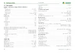
Number...................................................................................................................................................................................................... 2
Operating mode, adjustable.................................................................................................................................................active, passive
Functions ........................................ off, Ins. alarm 1, Ins. alarm 2, connection fault, DC- alarm
4)
, DC+ alarm
4)
, symmetrical alarm,
........................................................................ device fault, common alarm, measurement complete, device inactive, DC offset alarm
Voltage.............................................................................................................................passive DC 0…32 V, active DC 0/19.2…32 V
Analogue Output (M+)
Number...................................................................................................................................................................................................... 1
Operating mode................................................................................................................................linear, midscale point 28 kΩ/120 kΩ
Functions ...........................................................................................................................................................insulation value, DC offset
Current ........................................................................................0…20 mA (< 600 Ω), 4…20 mA (< 600 Ω), 0…400 μA (< 4 kΩ)
Voltage........................................................................................................................................ 0…10 V (> 1 kΩ), 2…10 V (> 1 kΩ)
Tolerance .........................................................................................................................................................................................±20 %
Interfaces
Field bus:
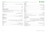
Interface/protocol....................................................................................................................................web server/Modbus TCP/BCOM
Data rate........................................................................................................................................................... 10/100 Mbit/s, autodetect
Max. amount Modbus requests ....................................................................................................................................................< 100/s
Cable length .................................................................................................................................................................................≤ 100 m
Connection ........................................................................................................................................................................................... RJ45
IP address .........................................................................................................................................................DHCP/manual 192.168.0.5
Network mask..................................................................................................................................................................... 255.255.255.0
BCOM address...........................................................................................................................................................................system-1-0
Function ..............................................................................................................................................................communication interface
ISOnet:
Number ISOnet devices ...................................................................................................................................................................... ≤ 20
Sensor bus:
Interface/protocol......................................................................................................................................................................RS-485/BS
Data rate................................................................................................................................................................................... 9.6 kBaud/s
Cable length ...............................................................................................................................................................................≤ 1200 m
Cable: twisted pair, one end of shield connected to PE................................................................... recommended: J-Y(St)Y min. 2x0.8
Connection ................................................................................................................................................................. terminals X1.A, X1.B
Terminating resistor at the beginning and at the end of the transmission path..............................120 Ω, can be connected internally
Device address, BS bus ....................................................................................................................................................................1…90
Switching elements
Number of switching elements..............................................................................................................................2 changeover contacts
Operating mode.......................................................................................................................................... N/C operation/N/O operation
Contact 11-12-14 ........................... off, Ins. alarm 1, Ins. alarm 2, connection fault, DC- alarm
4)
, DC+ alarm
4)
, symmetrical alarm,
......................................................................... device fault, common alarm, measurement complete, device inactive, DC offset alarm
Contact 21-22-24 ........................... off, Ins. alarm 1, Ins. alarm 2, connection fault, DC- alarm
4)
, DC+ alarm
4)
, symmetrical alarm,
......................................................................... device fault, common alarm, measurement complete, device inactive, DC offset alarm
Electrical endurance under rated operating conditions, number of cycles.................................................................................... 10.000
Contact data acc. to IEC 60947-5-1:
Utilisation category................................................................................................................... AC-13 / AC-14 / DC-12 / DC-12 / DC-12
Rated operational voltage .............................................................................................................. 230 V / 230 V / 24 V / 110 V / 220 V
Rated operational current ........................................................................................................................... 5 A / 3 A / 1 A / 0.2 A / 0.1 A
Rated insulation voltage ≤ 2000 m NN ........................................................................................................................................... 250 V
Rated insulation voltage ≤ 3000 m NN ........................................................................................................................................... 160 V
Minimum contact rating ...................................................................................................................................... 1 mA at AC/DC ≥ 10 V


