


Function
Function
iso685-D-B_D00177_05_M_XXEN/07.2017
11
The insulation monitoring device is able to measure the insulation resistance reliably and
precisely in all common IT systems (unearthed systems). Due to various applications, sys-
tem types, operating conditions, application of variable-speed drives, high system leaka-
ge capacitances etc., the measurement technique must be able to meet varying
requirements in order to ensure an optimised response time and relative uncertainty.
Different measurement profiles which can be selected from a setup menu allow optimum
adaptation of the measurement technique to the specific application.
If the preset response value falls below the value of Alarm 1 and/or Alarm 2, the associa-
ted alarm relays switch, the LEDs Alarm 1 resp. Alarm 2 light and the measured value is
shown on the LC display (in case of insulation faults in DC systems, a trend graph for the
faulty conductor L+/L- is displayed). If the fault memory is activated, the fault message
will be stored. Pressing the reset button, resets the insulation fault message, provided
that the insulation resistance is at least 25 % above the preset response value. As
additional Information, the quality of the measuring signal and the time required to up-
date the measured value are shown on the display. A poor signal quality (1-2 bars) may
be an indication that the wrong measurement profile has been selected.
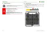
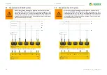
The insulation monitoring device has an internal system isolating switch, which makes it
possible to operate several ISOMETER®s in coupled IT systems. For this purpose, the
ISOMETER®s are connected via an Ethernet bus. The integrated Isonet function ensures
that only one ISOMETER® is actively measuring at a time, while the other devices are com-
pletely isolated from the system and waiting in standby mode for measuring permission.
3.4 Interfaces
• Communication protocol Modbus TCP
• BCOM for Bender device communication via Ethernet
• BS bus for communication of Bender devices (RS-485)
• Integrated web server for reading out measured values and for parameter setting
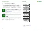
3.5 Self test
After switching on the supply voltage, the ISOMETER® automatically and continuously
checks all internal measuring functions, the components of the process control such as
the data and parameter memory, as well as the connections to the IT system and earth.
The self test can also be activated manually by means of the test button to check the func-
tions of the relays (depending on the configuration) or it can be selected via the "Control"
menu (refer to
).
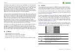
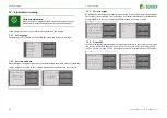
The progress of the manual self test is shown on the LC display by a bar graph. Depending
on the conditions in the IT system being monitored, the self test is completed after
15…20 seconds. The device then returns to the standard mode (measurement mode)
and the actual measured value will be displayed after the measuring time has expired.
The display shows the message
Initial measurement
until the first valid value is meas-
“Initial measurement” on page 29
If a fault is detected during the self test, the respective LEDs of the device light (refer to
). In addition, the respective message will be indicated on
the display and a previously programmed output will provide the respective signal.
The test has been run and the result was positive.
The test has been run and the result was negative.
The test is not available and is not carried out
(e.g. due to specific device settings).
The test is running.
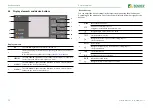
TEST
√ Measurement
Coupling
Earth connection
Outputs
33 %
√


