


Device communication
Device communication
iso685-D-B_D00177_05_M_XXEN/07.2017
48
11.5 BS bus
www.bender.de/manuals
.
Master-slave principle
The BS bus works according to the master-slave principle. This means that the measuring
device operates as the MASTER, while all sensor devices operate as SLAVES. The master is
responsible for the communication that is necessary for the measuring function. The mas-
ter also provides the required bus bias voltage for the operation of the BS bus. The meas-
uring device on the BS bus is the master and has address 1. All sensor devices connected
to the BS bus require unique addresses.
Addresses and address ranges on the BS bus
Address 1 is assigned to the master. All sensor devices receive unique addresses starting
with address 2, assigned in consecutive order without gaps. In the event of a device fail-
ure, a maximum gap of 5 addresses is permissible.
RS-485 specifications/cables
The RS-485 specification restricts the cable length to 1200 m and requires a daisy chain
connection. The number of devices on the BS bus is only limited by the BS bus master.
Use twisted pair, shielded cables for bus cabling. For example, cable type J-Y(St)Y
n x 2 x 0.8 is suitable. The shield must have a single-ended connection to earth. The BS
bus must be terminated at both ends with terminating resistors (120 Ω, 0.25 W). The ter-
minating resistors are connected in parallel to the terminals A and B. Some devices fea-
ture integrated terminating resistors and can be activated or deactivated via the "R"
button.
When using interface converters, a galvanic separation is required.
The compatibility of the BS bus and the BMS bus is restricted!
CAUTION
Cable routing
The optimum cable routing for the BS bus is a double-terminated bus topology. The length
of the branch line is limited to 1 m. These branch lines do not have to be terminated.
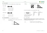
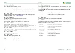
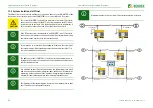
Bus topology examples:
Termination
1
Master
Terminating resistor activated via switch on device (ON) or external termi-
nating resistor between terminals A and B
2
Slave
Terminating resistor deactivated via switch on device (OFF)
3
Slave
Terminating resistor activated via switch on device (ON) or external termi-
nating resistor between terminals A and B
Only the first and last device in one line may be terminated. Therefore,
check all devices.
2
2
2
3
2
2
2
2
2
2
3
2
2
2
3
CAUTION


