


iso685-D-B_D00177_05_M_XXEN/07.2017
44
Device communication
11. Device communication
11.1 Ethernet interface
The Ethernet interface can be used for communication with Modbus, web server and
BCOM.
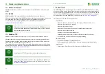
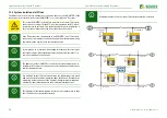
11.2 BCOM
BCOM is intended for communication between Bender devices via Ethernet.
All devices that communicate via BCOM must have the same system name. Devices can
be organised in subsystems. Each device requires an individual device address.
For more information regarding BCOM, refer to the BCOM manual (D00256)
at
11.3 Modbus TCP
Modbus is an international widely used protocol for data transfer between devices.
All measured values, messages and parameters are stored in virtual register addresses.
Data can be read out with a read command on the register address. With a write com-
mand, data can be written into a register address.
The register addresses of the individual measured values und parameters can be found
in the manual "iso685-D Annex A" with the title "ISOMETER® iso685 device family - Mod-
bus settings" at
When address 0 has been set for communication via BCOM the device can
be accessed via the network (e.g. for parameter setting, etc.) but it cannot
communicate with other devices.
A maximum of 5 TCP/IP connections can be used simultaneously.
In order to be able to parameterise the device externally via Modbus, the
menu item "Allow" must have been set in the "Write access" menu (see
11.4 Web server
The ISOMETER® has an integrated web server which displays ISOMETER® data comforta-
bly on every PC via a web browser. The web server can be used to read out measured val-
ues and parameterise the ISOMETER®s. You can access the web server by entering the IP
address of the ISOMETER® into the browser (e.g. http://192.168.0.5). The Info menu provi-
des information about the ISOMETER®‘s IP address (see
).
The web server offers the following functions:
• Visualisation
• Indication of device information (e.g. device type, software version, etc.)
• Indication of current device settings.
• Indication of alarm messages.
• Indication of the Modbus information of the individual parameters.
• Indication of the interfaces in use.
• Overview of the current measured values.
• Detailed graphic representation of the insulation resistance (isoGraph).
• Fast and simple visualisation without any programming.
• Parameter setting
• Easy and fast parameter setting of the device.
• Easy assignment and edition options of device and measuring channel texts.
• Maintenance
• Data storage of specific events for fast support by Bender Service.


