


iso685-D-B_D00177_05_M_XXEN/07.2017
10
Function
3. Function
3.1 Features
• ISOMETER® for IT AC systems with galvanically connected rectifiers or inverters and
for IT DC systems (IT = unearthed systems)
• Automatic adaptation to the existing system leakage capacitance
• Combination of
and other profile-specific measurement methods
• Two separately adjustable response value ranges of 1 kΩ…10 MΩ for alarm 1 and
alarm 2
• High-resolution graphic LC display for excellent readability and recording of the
device status
• Connection monitoring (monitoring of the measuring lines)
• Automatic device self test
• Graphical representation of the insulation resistance over time (isoGraph)
• History memory with real-time clock (buffer for three days) for storing 1023 alarm
messages with date and time
• Current or voltage output 0(4)…20 mA, 0…400 µA, 0…10 V, 2…10 V (galvanically
separated), which is analogous to the measured insulation value of the system
• Freely programmable digital inputs and outputs
• Remote setting of certain parameters via the Internet
(Option; COMTRAXX® gateway)
• Worldwide remote diagnosis via the Internet (made available by Bender Service
only)
• RS-485/BS (Bender sensor bus) for communication with other Bender devices
• ISOnet: Internal separation of the ISOMETER® from the IT system to be monitored
(e.g. if several IT systems are interconnected)
• BCOM, Modbus TCP and web server
3.2 Product description
3.2.1 General product description
The ISOMETER® is an insulation monitoring devices in accordance with IEC 61557-8 for IT
systems. The devices are universally applicable in AC, 3(N)AC, AC/DC and DC systems. AC
systems may include extensive DC-supplied loads (such as rectifiers, inverters, variable-
speed drives).
*
3.2.2 Special characteristics of ISOMETER® iso685-S-B with front panel
The ISOMETER® iso685-D-B and iso685W-D-B are devices of the iso685 device family with
integrated display. This manual applies in full to these ISOMETER®s.
The ISOMETER® iso685-S-B and iso685W-S-B are sensor variants of the iso685 device fam-
ily without display. The only difference between these variants and the ISOMETER®s
iso685-D and iso685W-D-B is that they do not feature a display.
The ISOMETER®s iso685-S-B and iso685W-S-B must be used in combination with a front
panel because the devices are operated via the front panel. The operation of the front
panel is equal to the operation of the ISOMETER®s with integrated display, which is
described in this manual.
Hereafter, the ISOMETER®s with integrated display are described. This description is sim-
ilar to the combination of ISOMETER® sensor variants and the front panel FP200. The de-
vices to which this manual applies will be referred to as ISOMETER®s hereafter.
3.3 Functional description
The insulation monitoring device continuously monitors the entire insulation resistance
of an IT system during operation and triggers an alarm when the value falls below a pre-
set response value. To obtain a measurement the device has to be connected between
the IT system (unearthed system) and the protective earth conductor (PE). A measuring
current in the µA range is superimposed onto the system which is recorded and evalu-
ated by a micro-controlled measuring circuit. The measuring time is dependent on the
selected measurement profiles, the system leakage capacitance, the insulation resistance
and possible system-related disturbances.
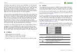
The response values and other parameters are set using a commissioning wizard or via
different setup menus using the device buttons and a high-resolution graphical LC dis-
play. The selected settings are stored in a permanent fail-safe memory. Different
languages can be selected for the setup menus as well as the messages indicated on the
display. The device utilises a clock for storing fault messages and events in a history
memory with time and date stamp. The settings can be protected against unauthorised
modifications by entering a password. To ensure proper functioning of connection mo-
nitoring, the device requires the setting of the system type 3AC, AC or DC and the requi-
red use of the appropriate terminals L1/+, L2, L3/-.
Only the sensor variant (ISOMETER® iso685-S-B or
iso685W-
S-B) can be
connected to the front panel. Connection to the display variant
(ISOMETER® iso685-D-B or iso685W-D-B) is not possible.


