-8-
[ 3 ] MAIN CONTROLLER AND ARM INSTALLATION
The instructions given below are for mounting the main controller assembly on wood studs.
Should the PHOT-XIIs 505 be mounted in a manner other than what is specified here, the
wall and the strength of the hardware used must be checked and verified as being adequate to
withstand a 45kg shear load and a 200kg withdrawal force at each of the three ( 9 x 75mm) lag
screws. When using concealed wiring, a flush mounted junction box with the necessary conduit
and wiring must be pre-installed at 1165mm from the floor.
A. ARM MOUNTING BRAKET
Make sure the power supply is turned OFF at the circuit breaker panel.
1. Tape the wall mounting template to the wall, positioning it so that the holes for mounting plate
lag screws are aligned with the vertical studs.
NOTE :
Confirm that the location of concealed wiring matches to the access hole of wall plate
template.
2. Mark the hole locations for the arm mounting bracket lag screws.
3. Use a 3/16" (5mm) dia. drill to make a pilot hole approximately 50mm deep for each mounting
lag screws.
Do not use a drill larger than 5mm dia. for these holes.
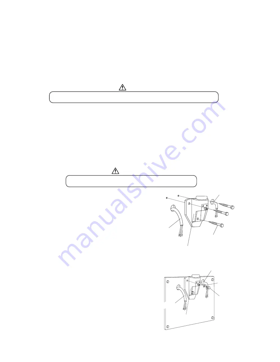
4. Using three lag screws ( 9 x 75mm) with washers in
top mounting holes and in lower mounting hole, mount
the arm mounting bracket on the wood stud.
(Fig.3-1)
WARNING
CAUTION
Fig.3-1
Arm Mounting Bracket
Installation
WALL PLATE INSTALATTION (OPTION)
1. Place the wire through the hole into the stud mount
wall plate and mount the plate to the stud with
four ( 9 x 75mm) lag screws.
DO NOT FULLY TIGHTEN.
2. Using three bolts (M8 x 20mm) with washers in top
mounting holes and in lower mounting hole, mount
arm mounting bracket to wall plate.
(Fig.3-2)
Arm Mounting
Bracket
Wires
( 9 x 75)
Lag Screw
Fig.3-2
Arm Mounting Bracket Installation
on Wall Plate (Option)
ø
ø
ø
ø
Arm Mounting
Bracket
(M8x20)
Bolt
Flat Washer
Wires
Interconnecting
Interconnecting
Power Supply
Power Supply
Wires
Wires
Summary of Contents for PHOT-X IIs 505
Page 2: ......
Page 35: ...NOTE...


