SECTION 5 1 8-4 1 1 - 100
.. Transmitter-Receiver,
2A-order
one for
each station equipped with hands-free answer
on intercom (HF AI). Also order one 20128
transformer for each transmitter-receiver
•
Set, Telephone, 502BM- order one for each
rotary dial intercom-only station.
•
Set, Telephone, 2502BM-order one for each
TOUCH-TONE intercom-only station.
•
Mounting, Apparatus, llOA-order one for
each two off-premises stations.
•
Unit, Key Telephone, 420A-order one for
each off-premises station.
•
Diode, 518A-surge protection for off-premises
station. Order two per station.
Note:
If 6B KTS system has off-premises
extensions, ringing voltage must be supplied
to the llOA apparatus mounting from the
associated key system.
572A1 KSU
3.0 1
The 572A1 KSU can be mounted in a 16C
apparatus mounting, or in available space
on a 23-inch relay rack or other suitable mounting.
The KSU requires approximately 13 inches of vertical
space. If the KSU is to be floor mounted in a
16C apparatus mounting, use a ED-95023-70 Group
10 floor stand. For information on other apparatus
mountings, and associated mounting hardware, refer
to Section 463-140-100. If a 117C cover is to be
used with the 16C apparatus mounting, install the
bracket supplied with the cover as follows:
(1) Position backboard of 16C as desired and
mark location of fasteners using double-ended
keyhole slots. Gate can open to right or left.
(2) Install fasteners, letting heads protrude about
1/4 inch.
(3) Place mounting on fasteners.
(4) Before tightening top two fasteners, slide
cover bracket between backboard and the
mounting surface.
The slots in the bracket
should engage the top fasteners.
(5) Tighten all fasteners.
Page 10
The center bar of
the
16C apparatus mounting
must be removed.
3.02
Incoming CO/PBX line connections and the
required leads to the stations are brought
into the KSU using A25B connector cables plugged
into the rear of the KSU. The number of cables
required will depend on the number and codes of
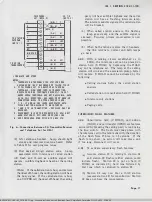
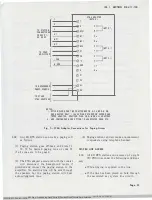
the stations to be installed. Fig. 31, 32, 33, and
34 show the wiring between the j acks on the front
of the KSU and the plugs on the rear. The plugs
are marked PO to P13. PO is dedicated to future
expansion and is not used in this application.
3.03
The distant end of the connector cables from
P1 through P12 can be terminated on the
yellow field of a centralized key system distribution
field; or a 184C1 backboard, which was designed
for use with the 6B KTS, can be used.
If the
184C1 backboard is used, these connector cables
must have a connector at each end for connecting
to the backboard and the KSU.
3.04
The connector cable from P13 contains the
tips and rings of the incoming lines
ahead
of the line circuits and is routed to access these
leads instead of to the 184C1 backboard.
3.05
Each connector cable from P1 through P10
of the 572A1 KSU contains the leads for
five station codes-PH contains the last two.
Connector cables should be run between the KSU
and the 184C1 backboard depending on the codes
required and as shown in Table E and Fig. 2.
The one exception is when paging access is supplied.
If the system is small enough, requiring only one
connecting block
and
paging access is supplied,
connect the cable from P9 of the KSU to connector
5 of block A (Fig. 35). Under this arrangement,
station codes 25-29 cannot be used.
If future
expansion requires the addition of block B and the
use of station codes 25-29, connect the cable from
P4 of the KSU to connector 5 of block B. The
cables from stations 25-29 must be cut down on
column H of block B. If the original installation
requires more than one block, the cables from the
blocks to the KSU should be terminated as shown
in Table E and Fig. 2.
Note:
If override is furnished, the coding
of stations 10 through 19 can vary. If the
override toggle switch is in the "10-19" position
the codes will be 10 through 19. If the switch
is in the "10-11" position, codes 12 through
BSP 518·411·100·i01_1978·08·10.jpg Scanned by Frank Harrell, (Cowboy Frank) Castle Rock, Colorado Oct 15, 2012 20:57:48


