ISS 1 , SECTION 5 1 8-4 1 1 - 1 00
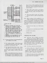
TABLE D
68
KEY TELEPHONE SYSTEM O PTIONS
OPTION
KTU
OPTION PLUG OR SWITCH POSITION
A - Continuous
A-B (1st and 2nd stations)
Ring
484A
D-E (3rd and 4th stations)
(Note 1)
B - Interrupted
B-C (1st and 2nd stations)
Ring
E-F (3rd and 4th stations)
C - Single-spurt
A-B,D-E
Audible Ringback
486A
(Note 2 )
D - Repeated Audible
B-C, E-F
Ringback
E - Fast Disconnect
B-C (1st Circuit)
(CSBR)
488A
E-F (2nd Circuit)
F - Slow Disconnect
A-B (1st Circuit)
(ESS Office)
D-E (2nd Circuit)
G
- Without Paging
Paging
Switch Off (Factory-provided)
Access
Access
Switch
H - With Paging
(Note 3)
Switch ON
Access
J
- Two Station Override
Override
"10
&
11" (Factory-provided)
Switch
K - Ten Station Override
(Note 3)
"10-19"
Notes:
1. If HF AI is provided, install option A for station involved. If one of
paired circuits has option A, other stations will have it
2. If any station has HF AI, system must have option
C.
3. The Paging Access and Override Option switches are located on the rear
of the 572A1 KSU.
•
Generates required system tones
and lamp wink, and also sets other system
timing standards.
•
Switches the tones to the talking links
•
Interfaces the control signals from the line
and station circuits to the controller
•
Switches the TOUCH-TONE receiver to the
talking links as required
•
The timing generator produces timing signals
required by the system, such as lamp flash
Refer to Table B for an outline of the tones used
in the 6B KTS. The 486A KTU is installed in J3.
D.
487A KTU-Battery Feed Circuit
2 . 1 7
Each 487A KTU provides the de voltages
for two links. The KTU for the first two
links is installed in J4; if a third and fourth link
is provided, another KTU must be installed in J5.
Page 7
SSP 518-41 1·100-i01_1978-08-07.jpg Scanned by Fra n k Harrell, (Cowboy Frank) Castle Rock, Colorado Oct 1S, 2012 20:56:50


