35
EESX20 and EESX30
Release 1.5 04/2020
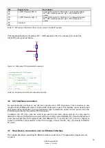
3.7.4
Magnetics Coupling
– 1000Base-TX
Figure 3-13: Capacitive Coupling - Circuit Diagram
3.8 Layout recommendations
Some recommendations to adapt the EESX-Evaluation-Board design to your application design.
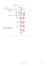
A) Quick switches
- The mode switches SW403 and SW601 can be removed in custo
mer’s application design - if only using TX-
OR
FX- (SFP or DSC) Mode. (Without Mode switches connect the open nets to the correct net or potential).
Just as can be removed the (signal path) Quick switches IC701 up to IC708 for ports 1 to 4 and IC801 up to
IC808 for ports 5 to 8. Connect the signal pathes coming from the switching IC directly to the TX or FX port.
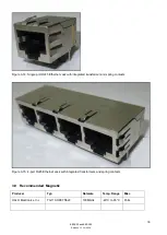
B) Ethernet Jack for twisted pair
- Use Ethernet Jacks with spring contacts for twisted pair copper mode to improve galvanic contact to metal
housing due to EMC reasons.
C) Ethernet Jack with integrated transformer for twisted pair
- Use RJ45 Ethernet Jacks with integrated transformers to reduce space and to facilitate an easier electrical
isolation on the PCB
– if isolation of 2250 kV DC between Ethernet port signal contacts and potential of the
EESX module (Ground and all other nets) according IEEE standard 802.3 is required.
- For Instance the CO1502 at GE port 2 on EESX-Evaluation-Board has an integrated transformer for Gigabit-
and Fast-Ethernet applications.


