INSTALLATION AND STARTUP
22-6
Belanger, Inc.® * PO BOX 5470. * Northville, MI 48167-5470 * Ph (248) 349-7010 * Fax (248) 380-9681
1MANUL220
Chapter 22 Initial Startup
SCC and Other Components
4)
Flush air line for 1 minute and connect to system air regulator.
Set air pressure to 105 psi and check HMI (E-1063 Human Machine Interface) for E-Stop condition.
Troubleshoot E-Stop circuit if necessary.
5)
Check the Fault Screen on the HMI (E-1063 Human Machine Interface) for any faults and troubleshoot if needed.
6)
Turn down air pressure while someone watches the Monitor Inputs field on the HMI (E-1063 Human Machine
Interface Monitor Inputs Screen) for the LOW AIR Input to turn off.
Note:
The LOW AIR Input should turn off at 75 psi and lower.
Adjust the pressure switch on the System Pneumatic Regulator Assembly to achieve this condition.
7)
Reset the air pressure to 105 psi.
8)
Turn off disconnect at each electrical panel and verify e-stop trips. (MCC, Dryer, Optional Wheel Cleaner Pump
Panel, other E-Stops, etc.).
9)
Flush freshwater line to FreeStyler®,
Connect the line and turn it on.
10)
Perform the appropriate startup procedure on all optional equipment if not already done. (Dryer, RO, Reclaim, Spot
Free, Wheel Cleaner etc.)
Note:
Be aware that when wheel movement is triggered manually, the water will come on. If you
do not wish to get wet, turn off the water main before moving the wheels.
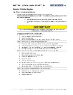
System Pneumatic
Regulator Assembly
Note:
CLEAN DRY AIR IS NECESSARY TO PROTECT YOUR
PNEUMATIC COMPONENTS.
Note:
An Air Dryer may be needed.
Note:
Verify that the optional system air compressor Cut In/Cut Out
settings are 1400 PSI Minimum.
Summary of Contents for FreeStyler
Page 1: ...FreeStyler Installation Startup FreeStyler Installation Startup 1MANUAL220 Rev14 ...
Page 2: ......
Page 4: ......
Page 12: ......
Page 13: ... Chapter 1 Introduction Chapter 1 Introduction ...
Page 14: ......
Page 26: ......
Page 28: ......
Page 31: ... Chapter 3 Getting Started Chapter 3 Getting Started ...
Page 32: ......
Page 52: ......
Page 53: ... Chapter 4 Frame and Carriage Assembly Chapter 4 Frame and Carriage Assembly ...
Page 54: ......
Page 123: ... Chapter 5 Entrance and Exit Photo Eyes Chapter 5 Entrance and Exit Photo Eyes ...
Page 124: ......
Page 135: ... Chapter 6 Treadle Assembly Chapter 6 Treadle Assembly ...
Page 136: ......
Page 142: ......
Page 144: ......
Page 151: ... Chapter 8 MixStir Options Chapter 8 MixStir Options Triple Foam and High Pressure Wax ...
Page 152: ......
Page 163: ... Chapter 9 Reclaim Water Adapter Kit Option Chapter 9 Reclaim Water Adapter Kit Option ...
Page 164: ......
Page 167: ... Chapter 10 Booster Pump Assembly Option Chapter 10 Booster Pump Assembly Option ...
Page 168: ......
Page 174: ......
Page 175: ... Chapter 11 Bug Spray Applicator Option Chapter 11 Bug Spray Applicator Option ...
Page 176: ......
Page 183: ... Chapter 12 Undercarriage Options Chapter 12 Undercarriage Options ...
Page 184: ......
Page 191: ... Chapter 13 Water Softener Option Chapter 13 Water Softener Option ...
Page 192: ......
Page 205: ... Chapter 14 HydroBlade Assembly Option Chapter 14 HydroBlade Assembly Option ...
Page 206: ......
Page 226: ......
Page 249: ... Chapter 16 Signage Options Chapter 16 Signage Options ...
Page 250: ......
Page 253: ... Chapter 17 Onboard Dryer Option Chapter 17 Onboard Dryer Option ...
Page 254: ......
Page 258: ......
Page 259: ... Chapter 18 Spot Free Rinse R O Option Chapter 18 Spot Free Rinse R O Option ...
Page 260: ......
Page 264: ......
Page 265: ... Chapter 19 Trades Chapter 19 Trades ...
Page 266: ......
Page 270: ......
Page 271: ... Chapter 20 Electrical Chapter 20 Electrical ...
Page 272: ......
Page 282: ......
Page 284: ......
Page 293: ... Chapter 22 Initial Startup Chapter 22 Initial Startup ...
Page 294: ......
Page 320: ......
Page 321: ......


