background image

VISTA DIGITAL INKJET PRINTER MANUAL 

Beijing Innovation Technology Co.,Ltd.        PAGE 1  

www.jhfvista.com

        TEL

86 10 62950101 FAX

86 10 82410746 

1


CHAPTER PROLOGUE .................................................................................................................................. 5


1.1.

  D

ESCRIPTION

............................................................................................................................................. 5


1.2.

  S

AFETY 

P

RECAUTIONS

! W

ARNING

!............................................................................................................ 7


1.3.

  T

HE MODEL IMAGE OF 

V

ISTA 

I

NKJET 

P

RINTER

........................................................................................... 8


1.4.

  M

ANUAL 

C

ATALOGUE FOR 

V

ISTA 

I

NKJET 

P

RINTER

.................................................................................... 9


2


CHAPTER 2: EQUIPMENT STRUCTURE AND PERFORMANCE ....................................................... 12


2.1. C

OMPOSING

................................................................................................................................................. 12


2.2.

  S

YSTEM 

P

ERFORMANCE

........................................................................................................................... 12


2.2.1


Mechanism System:.......................................................................................................................... 12


.2.2.1.1  Media Movement System ................................................................................................................ 14


2.2.1.2 Carriage Movement............................................................................................................................ 14


2..2.2  Electric System .................................................................................................................................. 15


2.2.2.1 Electricity Control Diagram............................................................................................................... 15


2.2.2.2 Control Box Map ................................................................................................................................ 16


2.2.2.3


Heating System ............................................................................................................................. 17


2.2.3Ink Supply System................................................................................................................................... 19


2.2.4. The Control System .............................................................................................................................. 21


2.2.4.1 Computer Configuration Request: ..................................................................................................... 21


2.2.4.2. Boards, Connections and diagram .................................................................................................... 21


2.2.4.3    the control system of    electrical board image and connection for the control system................... 22


2.2.4.4.


O

PERATING 

I

NSTRUCTION FOR THE MACHINE SWITCHES

................................................................... 24


2.2.5. Maintenance ......................................................................................................................................... 26


3


OPERATION INSTRUCTION ...................................................................................................................... 28


Summary of Contents for Vista1000

Page 1: ... 2 2 SYSTEM PERFORMANCE 12 2 2 1 Mechanism System 12 2 2 1 1 Media Movement System 14 2 2 1 2 Carriage Movement 14 2 2 2 Electric System 15 2 2 2 1 Electricity Control Diagram 15 2 2 2 2 Control Box Map 16 2 2 2 3 Heating System 17 2 2 3Ink Supply System 19 2 2 4 The Control System 21 2 2 4 1 Computer Configuration Request 21 2 2 4 2 Boards Connections and diagram 21 2 2 4 3 the control system of ...

Page 2: ...5 Check the Raster Positioning System 31 3 2 6 Ink Supply 31 3 2 7 Start Printing 32 3 2 8 End Printing 32 4 THE WAY OF DEALING WITH THE IMAGE FOR THE VISTA SOFTWARE 33 4 1 DESIGN IMAGE 33 4 2 CHANGE THE IMAGE AS CMYK FORMAT 33 4 3 SETTING IMAGE SIZE 34 4 4 MERGE IMAGE LAYERS 35 4 5 SAVE THE IMAGE FILE 36 5 RIP SOFTWARE PHOTOPRINT GUIDE 38 5 1 INSTALL PHOTOPRINT 38 5 2 SET THE PRINTER 38 5 3 ADD I...

Page 3: ...ard Installation 50 6 3 THE APPLICATION FOR CONTROL SOFTWARE 50 6 3 1 Printer Configuration 50 6 3 2 Main Page 51 6 3 3 Main Menu 51 6 3 4 Keyboard Shortcuts 54 6 3 5 Default Parameter Shortcut icon 54 6 3 6 Printing Mode 56 6 3 7 The array of print heads 58 6 3 8 Automatic Vacuum cleaning 59 6 3 9 STATUS BAR 59 6 4 FIBER INSTALLATION 60 7 DAILY MAINTENANCE AND REPAIR 61 7 1 Operating environment ...

Page 4: ... TEL 86 10 62950101 FAX 86 10 82410746 7 3 3 Print Head Maintenance 64 7 4 THE MAINTENANCE FOR THE SYSTEM OF M MODEL 66 8 DAILY TROUBLESHOOTING 67 9 KONICA MINOLTA PRINT HEAD INTRODUCTION 73 9 1 HOW TO PROTECT THE PRINT HEAD 73 9 2 PRINT HEAD DESCRIPTION 75 9 3 THE INK INSIDE MOVEMENT DIRECTION 75 ...

Page 5: ...1 2 The media Solvent based flexes paper banner mesh vinyl and so on Any media manufacturer is ok but good quality media is strongly suggested to get great printing impact and long lifespan printing outdoors 1 1 3 The Ink Solvent based ink oil based ink UV ink this is up to the print head model and ink supply system and resolution Any ink manufacturer is ok but good quality ink is strongly suggest...

Page 6: ...ds 4 color 12 print heads 6 color Servo System AC DC Working Station WIN98 WINXP Printing Port PCI USB Shape M V A and so on Non Guarantee Spare Parts of the Equipment Print heads ink pumps filters and ink tubes 1 1 8 Warranty One year since the machine left factory 1 1 9 Non warranty Items The warranty doesn t cover the force majeure and user damage 1 1 10 Package Legs assembled and legs unassemb...

Page 7: ...gned accord with all the safety requirements of printing equipments But to ensure 100 safety the operator should follow the safety precaution and operation instruction of this manual and the improved version in future seriously Only the operator who is correctly trained and qualified to operation can be allowed to do installation maintenance Without JHF s written permission any modification deleti...

Page 8: ... it when it isn t used against the volatilization of the efficient components which may cause the ink and solution invalidation The invalid ink will damage the print head The ink should be shook before it will be used Please make sure there is no ink on the electric circuit board and cables lest circuit short or turn off It is strongly suggested that you turn off the general power before you disco...

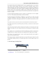
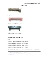
Page 9: ... V model KONICA print head image 1 4 A model KONICA print head 1 4 Manual Catalogue for Vista Inkjet Printer model VISTA10000 adopt KONICA KM512MN 14PL print head VISTA9000 adopt KONICA KM512LN 42PL print head VISTA8000 adopt KONICA KM256MN 14PL print head VISTA6000 adopt KONICA KM256LN 42PL print head The standard default for printer you can check the configuration demand on the standard default ...

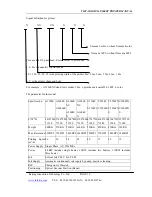
Page 10: ...ter for the model Specification A3308E A2604E A2606ES A2606E NS A2604E N A1606E NS A1604E N V3304F V3306FS V2504F V2506FS V2504FNV1804FN V2506FN S V1806FN S L W H 4410 800 1350 3760 800 1350 3760 800 1350 2760 800 1350 4750 930 1280 4100 930 1280 4100 930 1280 3350 930 1280 Weight 600KG 530KG 530KG 460KG 520KG 450KG 450KG 380KG Max Resolution 720DPI 720DPI 1440DPI 1440DPI 720DPI 720DPI 1440DPI 144...

Page 11: ...mm automatic manual feeding and collecting Media Suction Media Suction under the printing table Heating Pre heater and Post heater separate temperature control and display Drying Front Fan Head Maintenance Automatic Vacuum Cleaning Positive Cleaning Head Cover to keep head wet Media PVC Vinyl Mesh Non woven Textile File TIFF RGB CMYK BMP JPEG Interface High Speed PCI Card Data Transferring Optical...

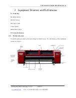
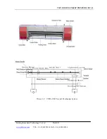
Page 12: ...X 86 10 82410746 2 Equipment Structure and Performance 2 1 Composing Mechanism System Electrical System Ink supply System Control System Maintenance System 2 2 System Performance 2 2 1 Mechanism System It includes media movement system and carriage movement system The structure map of the mechanism system is as follows ...

Page 13: ...VISTA DIGITAL INKJET PRINTER MANUAL Beijing Innovation Technology Co Ltd PAGE 13 www jhfvista com TEL 86 10 62950101 FAX 86 10 82410746 Picture 2 1 VISTA UM V model Mechanism System ...

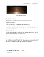
Page 14: ...ware For more details of the parameters adjustment in the software please refer to software explaining chapter Driven movement system It includes Reducer single phase motor and winding roller The media roller switch on the panel of the printer controls the movement of the driven movement system 2 2 1 2 Carriage Movement The Movement System of the Print head carriage is also named as Servo Control ...

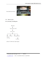
Page 15: ...MANUAL Beijing Innovation Technology Co Ltd PAGE 15 www jhfvista com TEL 86 10 62950101 FAX 86 10 82410746 Print Head Fixation Screws 2 2 2 Electric System 2 2 2 1 Electricity Control Diagram Picture 2 2 Electricity Control System ...

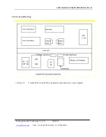
Page 16: ...PRINTER MANUAL Beijing Innovation Technology Co Ltd PAGE 16 www jhfvista com TEL 86 10 62950101 FAX 86 10 82410746 2 2 2 2 Control Box Map Picture 2 3 V model PCI sytem SPT510 print head machine Electricity Control diagram ...

Page 17: ...nology Co Ltd PAGE 17 www jhfvista com TEL 86 10 62950101 FAX 86 10 82410746 Picture 2 4 UM model PCI sytem SPT510 print head machine Electricity Control diagram 2 2 2 3 Heating System Picture 2 5 Heating System Diagram Note Heater controller namely thermostat ...

Page 18: ...ator blinking during self adjusting Parameter adjust button up increase button Parameter adjust button down decrease butto Replacement Button Self adjustor button Set ok Controller display Heater Controller Parameter Settings Illumination Initial Parameters press enter password to enter the system parameter Marks Meaning Option Scope Initial Parameter inty inty Heat Sensor Model See Pic 2 8 Pt 10 ...

Page 19: ...temperature setting value SV Press the increase switch the temperature setting value will add 1 and press the minish switch the temperature setting value SV will decrease 1 2 The temperature setting and alarm setting is same as initial parameters setup 3 Relay connection value and break value illumination If you set AH1 AL1 or AH2 AL2 the relay cannot work If you set AH1 AL1 or AH2 AL2 relay works...

Page 20: ... works the ink is going to the ink tank when is on the upper limit level the floater sensor gives the break signal ink supply is stopped During printing the ink in sub ink tank will falls gradually after the ink supply the ink level increases again It means the ink will be kept in a suitable scope to keep the printing works well Lack ink Alarm when the ink in the main ink tank is going finishing t...

Page 21: ...loose the button the air pump and electromagnetism valve all stop working now the A and C is thorough to keep the balance of ink box pressure 4 Cleaning the ink from the surface of print head and beginning working 2 2 4 The Control System The controlling system of VISTA printer consists of computer software included relevant electronic circuit board the controlling switch electronic cable etc 2 2 ...

Page 22: ...ter 2 2 4 3 the control system of electrical board image and connection for the control system make sure the connection of AB port is good Make sure the connection of FCC is good When you insert or pull out the PCI card make sure the computer is off After you installed PCI card must fix it use the screw Forbid to insert or pull out the yellow signal cable for the PCI card and high thick cable ...

Page 23: ... Power Input Switch Power Supply 2 Position Limit Switch Emergency Stop Switch 24V Power Input Step Motor Servo Card 3 Stepping Signal Output Driver 24V Output Control Signal Output 4 Ink Pump Power Cable Ink Pump 5 Floater Sensor Cable Raster Signal Cable Color Board 6 Vacuum Cleaning Signal Vacuum Cleaner Power Output Serial Port A 24V Power Input Servo Motor PC 7 Servo Signal Output 24V Output ...

Page 24: ... PAGE 24 www jhfvista com TEL 86 10 62950101 FAX 86 10 82410746 Picture 2 12 Electric distributor board connector diagram 2 2 4 4 Operating Instruction for the machine switches note the position of the switch for V model and UM model if different please peruse what you need ...

Page 25: ...ITAL INKJET PRINTER MANUAL Beijing Innovation Technology Co Ltd PAGE 25 www jhfvista com TEL 86 10 62950101 FAX 86 10 82410746 Picture 2 14 V Model operation switches diagram Picture 2 15 9 switch panel diagram ...

Page 26: ...itch 1 2 3 5 6 7 switches Press it down the light on it will turn on and it connects single phase power controlling the feeding and take up rollers Machine operation order To make sure if the printer is out of power Press down general power switch and the machine gets the electricity when the indicator light is on Open the computer to run the JHF Printing Management Press the print head switch dow...

Page 27: ...nd user can put the solvent into the antisepsis sponge and cover the tray below the print head carriage holder after stopping printing but with the print heads on the machine When you doing that please make sure the tray covers the print heads and absorb the magnet against the print head carriage holder It can last the print head wet for at most 8 hours if there isn t any space If there is any spa...

Page 28: ...controlling cable between the computer and printer and also check its other power cables and signal cables to make sure they are connected well and rightly 8 Install the printing software and RIP software with the computer 9 When turn on the printer please put the hand nearby the emergency switch to deal with the accident 10 Send a file to the printer to check the printing 11 Turn off the printer ...

Page 29: ...se make it sure that the distance switches work well It needs two people to operate Operator A operate the computer moves the carriage to right side by software the operator B press the right distance switch the carriage will stop immediately at normal condition And then press down the emergency switch and loose the right distance switch Repeat it to make it sure the right distance switch is ok A ...

Page 30: ...to block the outlet after the print head can jet Cleaning print head Clean the print head one by one with the cleaning solution Please keep the cleaning solution in the print head at least 10 minutes in order to get rid of the protection liquid inside the print head absolutely Additionally please let off the cleaning solution from the print head completely When installing or uninstalling the print...

Page 31: ...d the two sides should be fixed firmly Check the Raster sensor should be 1 2mm to the raster top edge Check raster if there is scar or there is ink oil on it 3 2 6 Ink Supply Supply the ink to the sub ink tank A Make sure all the ink tube is connected well B Turn on the printer general power C Connect the ink level sensor of each color to floater accordingly D Make sure 4 or 6 ink pumps to start w...

Page 32: ...ormally the ink will flow from the print head caused from the positive pressure 3 2 7 Start Printing Start printing Please print the required image according to the manual of the printing software 3 2 8 End Printing Finish printing exit the printing system software and then turn off the switch of the print head of computer of heating system of power supply close the breaker of the power supply and...

Page 33: ... image The users are recommended to use PHOTOSHOP 6 01 version software which is produced by ADOBE Company to design the image for printer This manual takes the PHOTOSHOP 6 01 as an example to explain to provide the image file for the printing system software As for the detailed usage of PHOTOSHOP please refer to the special book for Photoshop 4 1 Design Image The image designer uses suitable imag...

Page 34: ...of the image file which is set up in the computer should be in accordance with the size of printing image so the practical size of the image file should be adjusted Please refer to the following picture Note the image designer should finish the operation of this part so this manual won t introduce in detail For further detailed information please refer to the special book of PHOTOSHOP ...

Page 35: ...Layers The users may use more image layer when they design the image and they need to use the order in picture to merge the image layer Refer to image Pic 5 3 Click the right button on the arrowhead of the picture it will flip the menu please refer to the picture for this To choose merge order to put together all image layers If the users don t use more image ...

Page 36: ...e the file format as TIFF BMP EPS or JPEG in the dialog box of save then the name of the file can be modified be saved as TIFF because the saved image file have to set up type by MAINTOP software and then the image can be printer with the printing system software by the digital Note the file format must printer However the MAINTOP software typeset software can only identify the image file of TIFF ...

Page 37: ...VISTA DIGITAL INKJET PRINTER MANUAL Beijing Innovation Technology Co Ltd PAGE 37 www jhfvista com TEL 86 10 62950101 FAX 86 10 82410746 Pic 5 5 ...

Page 38: ... Choose the installation type to install the software we suggest the standard installation then click the next Choose the folder which is used for save the software If you accept the default folder a new folder will come automatically to save the software Click the next Click yes clean the presetting or click no save the primary presetting you must make sure the password for the dongle is right or...

Page 39: ... click the cancel Port choose FILE This operation will be deal with and save as the default file for your computer prt file When you set this port and after the Production Manager RIP the image it will begin to print while RIP while printing COM serial communication port this port only supported by CNC ROUTER LPT parallel port is always be used for the connection of printer and the computer USB Th...

Page 40: ...0 www jhfvista com TEL 86 10 62950101 FAX 86 10 82410746 Finish add the printer as the following image image 5 1 5 3 Add ICC align file Click the file in the menu open menu Production Manager and click the import reset in the coming menu Choose the FS_6C_Preset in the open look in ...

Page 41: ... imported 5 4 Set the print job Click the file in the Production Manager click add job in the coming menu the following image will come after finish the addition all of the operation can be add delete and change the attribute production manager image 5 3 More than one printer can be operated together if the computer is applicable Double click the operation name the image job properties will come a...

Page 42: ...ties 1 Arrange 2 Item 3 Content 4 Remark 5 Media size 6 The system will alarm when media width length excess the provision there must leave the blank in the front and the back the left and the right while print 7 the media width should nearly meet the width of the machine 8 Width 9 Set the width and the length 10 11 Distance margin and between space 12 13 Workgroup 14 Item 15 Content 16 Remark ...

Page 43: ...peration for the color alignment has been performed The output file must be applicable to the ink media and resolution dithering of the output equipment When you choose the configuration file must make sure all of the configuration file must be applicable for the standard matching Choose the ICC file from the disk 2 operation attribute We suggest you use color alignment file 34 Beforehand example ...

Page 44: ...n High DPI for high quality but it need more time 53 54 Note 1 click the advanced in the color alignment and click the solid color in the coming menu input ICC file the new menu will come the setting as the following image 55 56 57 58 59 60 image 5 5 61 Note 2 The printing label displays the correlative setting it is up to the output equipment the label model may be different When you change some ...

Page 45: ... to change the dicey color space Color management use the default color management ICC output configuration file choose the ICC configuration file to match the media fill the ink to the printer 位图 color space conversion mode Choose the space conversion model which exist in the bitmap image Vector color space transform model choose space model which was used in the vector object Information click t...

Page 46: ...s The number width high for connection All the spell The same width same high fixed width high superposition width 67 68 image 5 6 69 Label and sign 70 Item 71 Set Content 72 remark Color Choose K C M Y LC LM width Set the width Printing label Spelling the superposition line You can set the measure between the row and the tier Depend on the superposition you can banish the aperture between the div...

Page 47: ...k to control the ink density You can input the parameter in the compilation box image 5 7 74 Separate seldom use 75 Preview preview function 76 Set the default set it as default 5 5 Send the operation After you set the attribute in the photo print then click send 1 while set the network print the printer will print directly 2 when you choose the FILE to print photo print software will save the ima...

Page 48: ...ument 5 6 Control software and the connection of PHOTOPRINT software TCP IP web site 127 0 0 1 Port choose FILE 5 7 The notice for PHOTOPRINT The PHOTOPRINT software enclose the manual and the file references The operation notice as the following The image resolution pass number must match the printing control system while you deal with RIP in order to get the perfect effect The image resolution s...

Page 49: ...t the print head from concreting monitor the state of the print head and set the distance width between the image and the color bar Adjust the data of print head alignment and media feeding size during printing The printing direction can be set accordingly with option of unilateralist printing and bi directional printing mirror image printing Lighten the edge Use to lighten the pass line Automatic...

Page 50: ... PCI Card Driver 6 3 The application for control software 6 3 1 Printer Configuration Double click the shortcut mode JHF V3306FS V2 07En run the control software please choose the printing configuration file as the following Choose the V3306FS 180dpi V3306FS 240dpi V3306FS 360dpi choice gist the resolution must be the same as the image resolution which was deal with the RIP software and ICC Choose...

Page 51: ...d image Delete Choose the wanted job on the image list press Del button to delete the wanted job Print Preview If the file under the folder is changed a little please preview and refresh the image list File Exit Exit the software it will show a diagram to ensure if the printer will return to the print head protection place Reposition Initialize the PCI card the print head carriage will return to t...

Page 52: ...inting the print head carriage moves to cleaning terminal Pause Pause printing the print head carriage moves to cleaning terminal Continue Continue printing Cleaning Print head Cleaning print head Choose the details in the optional setting dialog box Printing Test Printing test bar Adjust the print head parameter accordingly Flash Turn on off pinhead flash to prevent the print head block Choose th...

Page 53: ...o the temperature change If don t choose permit the print head adjust electric pressure the print head voltage will not change Note When press down Read or Write switch and turn on printer the software system will automatically return to the automatically adjusting voltage status except that you don t choose the permit the print head voltage adjust function The voltage is the power of the ink jett...

Page 54: ...mally 6 3 4 Keyboard Shortcuts To efficient the operatin we offered keyboard shortcuts Ctrl Home Initialization Ctrl End Cleaning Ctrl Pause Pause Ctrl Move to left Ctrl Move to Right Ctrl Media back Ctrl Media forward 6 3 5 Default Parameter Shortcut icon In order to set the regular setting easily there is parameter column under the tool bar Path the path for the wanted job Pass printing mode at ...

Page 55: ...ting bar to adjust the printhead excursion parameter Item Aim Note Status Check the ink jetting ink break print head block Alignment Color alignment the adjustment for bi direction color alignment Stepping offset Repair adjustment should happen together each circulate of stepping motor Completely jetting 4 color 100 jetting need to check the ink capacity Testing output the square meter per hour Te...

Page 56: ...ity ink quantity By this test you can check the ink saturation and you can cancel one or more colors to test one or mixed colors full printing effect 6 3 6 Printing Mode Pass 1 2 3 4 6 8 12 16 pass optional Carriage Speed High middle and low speed optional Media feeding speed High middle and low speed optional Quantity Quantity for each printing job Horizontal mirror It is used for the double side...

Page 57: ...The color bar is put at the right side of the image or the left side of the image The unit is one jet dot distance Automatically vacuum suction during printing Automatic cleaning Non automatic cleaning Turn on off the color bar Frequency Cleaning one time every xx pass Times The times of the print head carriage moves through each cleaning Mode Cleaner use the vacuum cleaning to clean Flash Flash c...

Page 58: ... physical resolution of each print head Step Excursion The step excursion is different at different pass unit 1 4 printing point distance Acceleration Length During printing the acceleration deceleration speed of the carriage when it moves through the printed outs two sides unit one print pint distance Color Excursion Each print head has three parameter as the excursion value unit one printing poi...

Page 59: ...nter V2 07 setup V3306FS 240 180 360dpi ini uiCleaning 0 the carriage suck ink for the left uiCleaningWidth 2700 the width of carriage move 6 3 9 STATUS BAR POS xxxxx xxxx the absolute position of carriage on raster unit the printing point distance the relative position of the carriage on the raster unit mm PSS xx xx xxxxx printed out finished lines print out total lines printing status STS xxxxx ...

Page 60: ... distance Input the parameter you measured the system will account the stepping parameter automatically 6 4 Fiber Installation B A B A Two fibers A B used for connect the control card of the print head and PCI card as there is connect port of fiber for each control card There is Tx and Rx stick on the port While one end of the fiber plug into Tx then the other one should plug into Rx Please kindly...

Page 61: ... Operation Maintenance Requirement The task of the operation and maintenance need to be operated and maintained with professional operator or the operator who got training from our Company and to be certified qualified The user must do strictly according to this manual 1 Wear anti static device when touching circuits electric parts cable and print heads 2 Strictly prohibit pull out or insert any p...

Page 62: ...he Stop button on tool bar under the printing software and stop the carriage then check the circuit and make the trouble shooting 7 Before printing and after printing please clean the print head and make the print head in good condition Please use special cloth or paper with cleaning solution on it to wipe the print head when cleaning the print head It is suggested to do like this every day before...

Page 63: ...bes one time by special cleaning solution to get rid of impurity inside the tube and dry the cleaning solution inside new ink tube completely 11 Cleaning the vacuum cleaner The flexible tube with the vacuum cleaner will diminish after a long time which will deduct air power from the vacuum cleaner In this case changing a new flexible tube with the cleaner is necessary or clean the flexible tube wi...

Page 64: ...ong term maintenance is carried out with the state of work off 7 3 3 Print Head Maintenance You can adopt one or mixed the follow daily maintenance ways A Press and washing Press and washing ways include two important functions To clean the air and contamination in the spout To clean the contamination in the nozzle Such of way could increase the heat of ink supply pressing the ink until gush out t...

Page 65: ...ng This way for maintenance print head has two main functions Drive the more printing ink on the nozzle board drive the infectant on the nozzle board when the mop tube moving in the short distance when through the nozzle board and spout line nearly please notice that cannot touching the nozzle board Mop tube is a thin tube connected to the vacuum so the ink can be absorbed along the nozzle board E...

Page 66: ...ience G The covered hat This hat cover is a program which used during the print head doesn t work protect the nozzle board be destroyed by dust This hat is felicitous around the nozzle board and prevents the air and dust get into the nozzle board Some hats may have some liquid this is good for printing ink volatilization then the spout will be dry Vista printers design a special part to protect pr...

Page 67: ...d pc C Reason the driver doesn t work normal the driver warns error Procedure adjust the driver PID if It can t work well yet after changing please replace a new one D Reason the motor is broken Procedure please change the motor E Reason the servo card is broken Procedure change the servo card F Reason PCI card is broken Procedure change the PCI card Trouble the equipment doesn t print 1 The print...

Page 68: ...aster can t read the data Procedure Please check then make the different procedure accordingly There is not the test for the X speed step size Please test and reset Single color or several colors doesn t print B Reason 1 There is something wrong with the color distribution board 2 There is something wrong with the print head 3 There is something wrong with the print head communication cable Please...

Page 69: ...belt or change a new belt Reason The setting parameter of the software is not correct Procedure reset the parameter of the software Printer prints with mosaic Reason power supply cable is defected Reason the data cable is defected Reason the carriage shakes during printing Please check the carriage bearings or rail Reason the image resolution is too low The general power supply can t be turned on ...

Page 70: ...place a new filter Reason The ink quality is not good please change the better quality ink The ink position is not correct adjust the position of the sub ink tank The print head aging is serious please replace another print head The image of the printer is not clear and the image resolution is not good Reason there is something wrong with the software parameter setting Procedure adjust the paramet...

Page 71: ...e of the step motor is too long raise the step value in the software Ink pump doesn t supply the ink Reason The ink pump is broken Procedure Please replace the ink pump Reason the ink supply board is broken Procedure Please replace the ink supply board Reason the power of the ink supply is broken Procedure replace the power of the ink supply Reason the floater cable is broken Procedure replace the...

Page 72: ...switch Restart the computer and printer After you press down the emergency switch the software is still working if you take up the emergency switch it will crash the limit switch If the computer hanged or restarted during printing it is possible that the software will be out of control In this condition we suggest you turn off the printer and move the carriage to the middle of the rail and then re...

Page 73: ...r the defend static watch Forbid any ink jump on the electrical circle board Please make sure you must install the small print head well and right or else the signal can not be transfered open the print head packaging 1 open the packaging take out the print head plastic bag 2 hold the bottom of the plastic bag take out the print head from the placket 3 tear the label and keep it well image 9 1 Rem...

Page 74: ...iquid fall on the cover in order to avoid cankering Black latex cover for liquid like solvent ink Green latex cover for liquid like oil ink 5 Remove the tube Remove the tube which connect with the ink port in order to prevent the liquid like ink flowing if the ink has been supplied to the print head when you reconnect the ink tube to the ink port of print head You must make sure that the rudimenta...

Page 75: ...side movement direction Enter port and exit The enter port and the exit suitable for R and L electrical board ink supply and discharge ink The filter divide the ink bursa to two parts The front filter and the back filter At first time can push out the air in the ink channel It can also clean up the ink exist in the ink bursa Some unstable ink must be replacing in the scheduled time to clear out th...

Reviews: