background image


6A

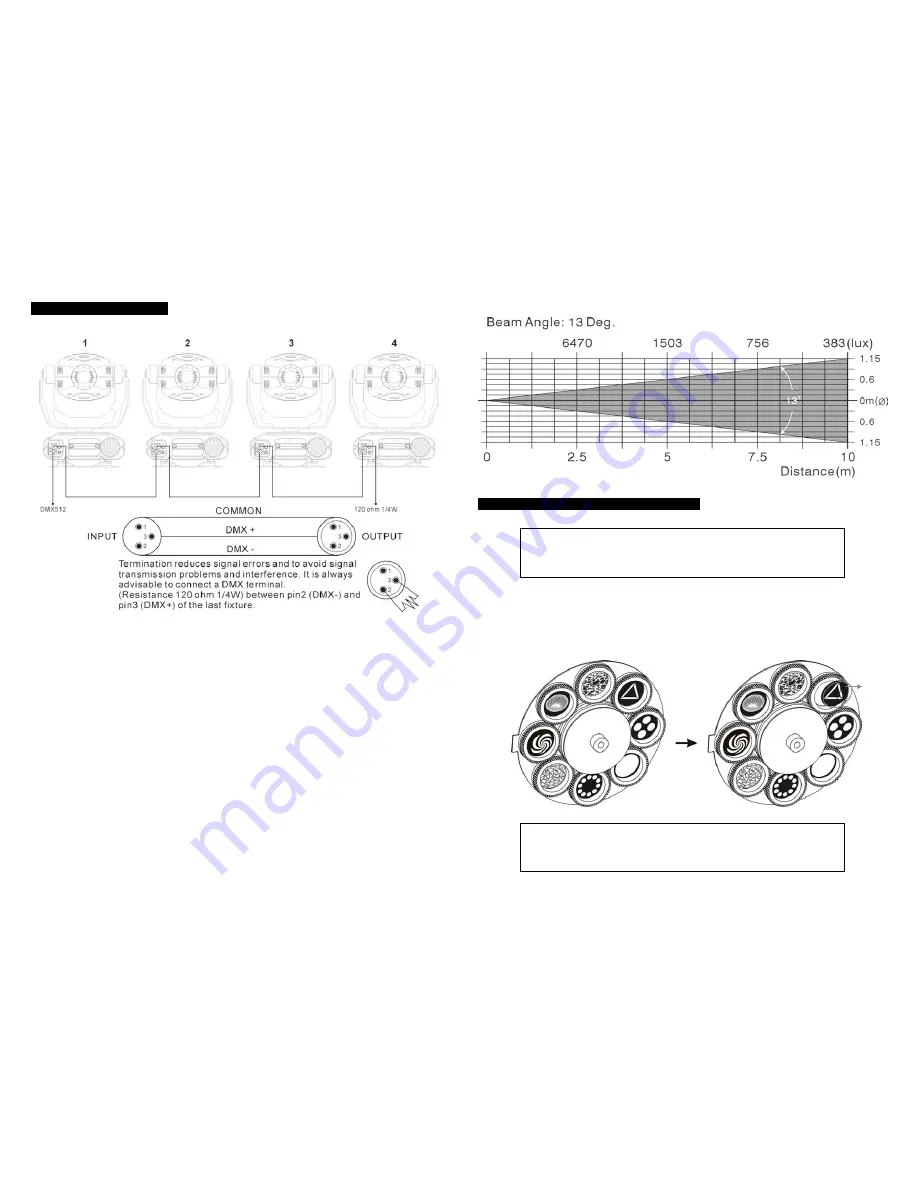
  5.5. DMX512 Connection 


The DMX512 is widely used in intelligent lighting control, with a maximum of 512 channels. 


1. If you use a controller with 5 pins DMX connector, you need to use a 5 to 3 pin adapter. 
2. At last unit, the DMX cable has to be terminated with a terminator. Solder a 120-ohm 1/4W 

resistor between pin 2(DMX-) and pin 3(DMX+) into a 3-pin XLR-plug and plug it in the 
DMX-output of the last unit. 

3. Connect the unit together in a “daisy chain” by XLR plug from the output of the unit to the 

input of the next unit. The cable cannot be branched or split to a “Y” cable. DMX512 is a 
very high-speed signal. Inadequate or damaged cables, soldered joints or corroded 
connectors can easily distort the signal and shut down the system. 

4. The DMX output and input connectors are pass-through to maintain the DMX circuit, when 

power is disconnected to the unit. 

5. 

Each lighting unit needs to have an address set to receive the data sent by the 
controller. The address number is between 0-511 (usually 0 & 1 are equal to 1).


6. 

The end of the DMX512 system should be terminated to reduce signal errors.


7. 

3 pin XLR connectors are more popular than 5 pins XLR.


3 pin XLR: Pin 1: GND, Pin 2: Negative signal (-), Pin 3: Positive signal (+)   

5 pin XLR: Pin 1: GND, Pin 2: Negative signal (-), Pin 3: Positive signal (+)


Luminous intensity:


2.1. Inserting/Exchanging rotating gobos   


DANGER! 

Install the gobos with the device switched off only. 

Unplug from mains before 

changing gobos!


Open the cover by loosening the fastening screw at the sides of the cover. 
If you wish to use other forms and patterns as the standard-gobos, or if the gobos are to be 
exchanged, remove the fixation ring with an appropriate tool. Remove the gobo and insert the 
new gobo. Press the fixation-ring together and insert it in the front of the gobo. 


CAUTION! 

Never unscrew the screws of the rotating gobo as the ball bearing 

will otherwise be opened!


Summary of Contents for MOVING HEAD SPOT

Page 1: ...WWW BEGLEC COM Professional Lighting Technology User Guide Please read these instructions carefully before use ...

Page 2: ...nging rotating gobos 3 Lamp 4 How To Set The Unit 4 1 Control Panel 4 2 Main Function 5 How To Control The Unit 5 1 Master Slave Built In Preprogrammed Function 5 2 Easy Controller 5 3 Universal DMX Controller 5 4 DMX512 Configuration 5 5 DMX512 Connection 6 Troubleshooting 7 Fixture Cleaning ...

Page 3: ...unction Please contact the nearest authorized technical assistance center Always use the same type spare parts z Don t connect the device to any dimmer pack z Do not touch any wire during operation as high voltage might be causing electric shock z 7 Fixture Cleaning The cleaning of internal and external optical lenses and or mirrors must be carried out periodically to optimize light output Cleanin...

Page 4: ...it to rain or moisture z Never touch bulb with bare fingers as it is very hot after using z Hot lamp explosion hazard Do not open the unit within five minutes after switching off z Do not start on the unit without bulb enclosure or housing are damaged z The housing the lenses or the ultraviolet filter must be replaced if they are visibly damaged z Do not look directly at the light while the bulb i...

Page 5: ...ing are a few common problems that may occur during operation Here are some suggestions for easy troubleshooting A The unit does not work no light and the fan does not work 1 Check the connect power and main fuse 2 Measure the mains voltage on the main connector 3 Check the power on LED B Not responding to DMX controller 1 DMX LED should be on If not check DMX connectors cables to see if link prop...

Page 6: ...nnected to the unit 5 Each lighting unit needs to have an address set to receive the data sent by the controller The address number is between 0 511 usually 0 1 are equal to 1 6 The end of the DMX512 system should be terminated to reduce signal errors 7 3 pin XLR connectors are more popular than 5 pins XLR 3 pin XLR Pin 1 GND Pin 2 Negative signal Pin 3 Positive signal 5 pin XLR Pin 1 GND Pin 2 Ne...

Page 7: ...tes at high pressure and there is a slight risk of arc tube rupture The risk increases with age temperature and improper handling of the lamp Do not use the lamp any longer than its specified life 5 Make sure the lamp is located in the center of the reflector for the best spot Adjust lamp position by screws A B and C i Channel 14 Pre programmed show pattern 1 DMX value 0 31 the fixture is still co...

Page 8: ...functions DOWN To go backward in the selected functions UP To go forward in the selected functions ENTER To confirm the selected functions Remote controller input By connect to the 1 4 microphone jack to control the unit for Stand by Strobe Next and Show 1 Slow Show 2 function Sensitivity To adjust the sound receiving sensitivity Microphone To receive audio signal for sound activation DMX input ou...

Page 9: ...nctions 1 STAND BY To blackout all the units 2 FUNCTION STROBE NEXT STROBE Under SHOW 1 and SHOW 2 mode the units will strobe in three different ways a Strobe in different gobos and colors b Synchronous strobe in white color c Two light strobe in white color Under SLOW mode press FUNCTION button to choose desired color and gobo It will change ten colors and then change one gobo 3 MODE SHOW 1 SLOW ...

Page 10: ...play will blink Use DOWN and UP button to change the DMX512 address Once the address has been selected press the ENTER button to setup or automatically return to the main functions without any change after 8 seconds To go back to the functions without any change press the MENU button again Show Mode Press the MENU button up To when the is showing on the display Pressing ENTER button and the displa...

Page 11: ...under ceiling Press the MENU button up to when the is blinking on the display Use the ENTER button to change to the mode display inversion It will automatically store after 8 seconds Or press the ENTER button again return to the mode display normal To go back to the functions press the MENU button Display normal mode for the fixture putting on the floor Display inversion mode for the fixture fixin...

Reviews: