background image

WARNING: High pressure hydraulic oil leaks can penetrate skin resulting in
injury, gangrene or death. Be sure to relieve any hydraulic oil pressure before
disconnecting any lines or pipes between spreader and tractor hydraulic system.
Check for oil leaks using a cardboard, never use hands.

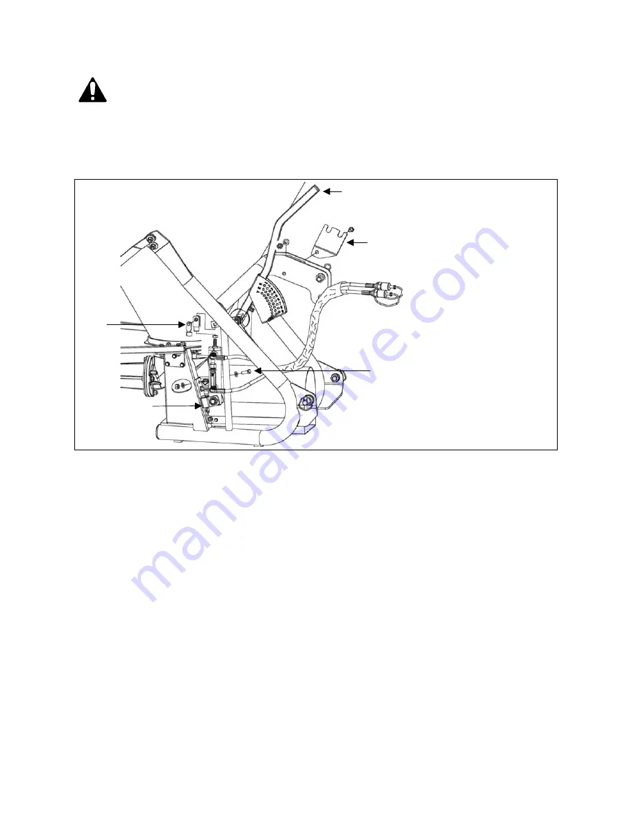
The hydraulic gate control is designed to be assembled to the right hand side of the
pendular spreader. To assemble, proceed as follows:
1. With the spreader unhooked from the tractor and positioned on stable ground, line

up the three holes on the cylinder bracket to the holes on the side plate by the
gearbox 

(see #1, fig. 16)

 and secure them with the M10x30 bolts, the Ø10 washers

and M10 nuts 

(see #2, fig. 16)

.

2. Remove the fixing pin that is assembled to the top cylinder yoke 

(see #3, fig. 16)

.

Line up the hole on the top cylinder yoke with the hole on the opening lever bracket
that is on the spreader. Slide the fixing pin through the holes and secure it on the
yoke.

3. Secure the hydraulic hose retainer plate with the slots facing outwards to the left of

the top hitch bracket through the bolt and secure it with the M12x30 bolts, the Ø12
washers and M12 lock nuts

 (see #4, fig. 16)

.


4. Remove the opening lever 

(see #5, fig. 16)

 from the frame as it will not function with

the hydraulic remote gate control assembled.

5. Position hydraulic hoses in a safe route towards the tractor and place the remotes

on the hose retainer bracket.

6. Tighten all hardware securely.

O

PERATION

23

BEFCO

T

URBO

-H

OP

O

PERATOR

S

 M

ANUAL

Fig. 16 - Hydraulic gate control.

1

2

3

5

4

Summary of Contents for TURBO-HOP 301-300

Page 1: ...BEFCO Operator s Manual TURBO HOP Pendular Spreaders 301 300 301 400 The operator s manual is a technical service guide and must always accompany the machine Manual 971 411B September 2014...

Page 2: ...r each have been selected using the following guidelines DANGER Indicates an imminently hazardous situation that if not avoided will result in death or serious injury WARNING Indicates a potentially h...

Page 3: ...chment 22 3 12 Optional Hydraulic Gate Control 22 3 11 Optional Rubber Insert 22 3 10 Optional Short Spout 21 3 09 Optional Agitator Extension 21 3 08 Optional Filter Grate 20 3 07 Uneven Terrain 17 3...

Page 4: ...or the operator CAUTION Unless otherwise specified all hardware is metric Use only metric tools on metric hardware Other tools that do not fit properly can slip and cause injury CAUTION Right hand an...

Page 5: ...anty covers defective material and workmanship The cost of normal maintenance or repairs for accidents or improper use and related labor will be borne by the owner 1 03 Model and Serial Number ID Atta...

Page 6: ...operating equipment read and understand the Operator s Manual and the safety signs see fig 2 2 Thoroughly inspect the implement before initial operation to assure that all packaging materials i e wir...

Page 7: ...shut the tractor down and thoroughly inspect for damage before restarting 7 To park the vehicle safely stop vehicle on a level surface not on a slope disengage PTO engage the parking brake stop the en...

Page 8: ...Fig 2 Safety decals implement replace immediately if damaged SAFETY PRECAUTIONS 8 BEFCO TURBO HOP OPERATOR S MANUAL left side right side right side left side...

Page 9: ...Safety decals driveline replace immediately if damaged SAFETY PRECAUTIONS 9 BEFCO TURBO HOP OPERATOR S MANUAL placed on outer shield placed on outer tube...

Page 10: ...responsible use of the equipment It must always be operated prudently following with great care the safety instructions laid out in this manual 1 The use of this equipment is subject to certain hazar...

Page 11: ...nd sharp turns to minimize tipping or loss of control Be careful when changing directions on slopes Do not start or stop suddenly on slopes Avoid operation on steep slopes 20 Pass diagonally through s...

Page 12: ...hardware needed for assembly will be found in the crate and the hardware bag of the machine Assembly will be easier if all parts are loosely assembled before tightening the hardware To assemble the p...

Page 13: ...allow for the lever to open and close properly without interference with the quick hitch Place the opening lever in position 2 see 2 fig 4 on tractors not equipped with a quick hitch in order to facil...

Page 14: ...ns clockwise and category 1 three point hitch or category 1 quick hitch Never use with tractors over 60 HP WARNING Never attempt to attach the implement to the tractor or make adjustments to it withou...

Page 15: ...end of the driveline is connected securely with the locking pin Connect the driveline shielding chains to the tractor and to the implement to prevent the protective shielding from rotating during ope...

Page 16: ...ne and securely in place 8 Making sure the proper attire is worn Avoiding loose fitting clothing which can become entangled Wearing sturdy tough soled work shoes and protective equipment for eyes hand...

Page 17: ...wing factors into account The quantity of material distributed per acre depends on the following factors 1 Tractor ground speed 2 Unit weight and size of the material to be spread 3 Spreading width 4...

Page 18: ...nding on the type of material you are trying to spread With the standard spout mounted the spreader will spread powdered materials between 17 and 20 and granular materials between 39 and 47 see fig 8...

Page 19: ...in a corner at a distance equal to of the total spread width away from the edge of the field Spread first around the perimeter of the field After covering the perimeter drive the tractor in parallel p...

Page 20: ...of approximately 6 5 and still drop material in rows roughly 3 wide see fig 11 3 07 Uneven Terrain WARNING Be careful of roll over when operating tractor and spreader over uneven ground The following...

Page 21: ...k 3 08 Optional Filter Grate The filter grate see fig 12 is a simple bolt on accessory ideal for filtering clots and foreign objects from the material being spread 3 09 Optional Agitator Extension The...

Page 22: ...as damp fertilizer or peat The rubber insert provides a high viscosity surface that lets humid material flow through the spout better 3 12 Optional Hydraulic Gate Control The hydraulic gate control al...

Page 23: ...rs and M10 nuts see 2 fig 16 2 Remove the fixing pin that is assembled to the top cylinder yoke see 3 fig 16 Line up the hole on the top cylinder yoke with the hole on the opening lever bracket that i...

Page 24: ...or only to the right the optional directional attachment see fig 17 20 improves accuracy when spreading in either direction To assemble unscrew the standard spread deflector and screw in the left righ...

Page 25: ...n place with the help of the locking nut To assemble unscrew the spread deflector screw in the locking nut screw the spout to desired position and use locking nut to tighten OPERATION 25 BEFCO TURBO H...

Page 26: ...operator to predetermine the desired opening of the distribution unit There are three lines of holes marked with letters R S T see fig 23 Each line has 9 holes which are offset by 4 mm from one anoth...

Page 27: ...m Nitrate 595 591 585 569 554 538 512 487 462 414 366 318 284 249 216 185 154 124 103 83 62 49 35 21 8 7 694 689 683 665 646 628 598 568 539 483 426 370 331 291 252 216 180 145 120 97 73 57 41 25 7 5...

Page 28: ...445 382 319 255 212 170 125 95 66 37 6 2 1298 1288 1271 1248 1227 1204 1155 1104 1055 978 900 824 733 646 557 477 399 319 265 211 156 119 83 46 5 1731 1717 1695 1665 1636 1606 1540 1472 1406 1304 1201...

Page 29: ...211 167 135 104 72 52 30 11 5 773 692 610 541 471 401 343 282 223 180 139 96 70 41 14 3 7 39 Wheat 201 170 140 114 88 62 49 36 22 16 10 4 8 7 235 199 163 133 103 73 57 42 26 19 12 4 7 5 282 238 196 1...

Page 30: ...ing to perform maintenance 6 Never work under equipment unless it is blocked securely 7 Always use personal protection devices such as eye hand and hearing protectors when performing any service or ma...

Page 31: ...l level with dipstick see fig 24 Use SAE 90W lubricant After each use 1 Be sure to thoroughly wash the machine without using excessive pressure especially on the moving parts It is particularly import...

Page 32: ...n the driveline manual IMPORTANT Always check driveline length during initial setup and when connecting to a different tractor In the collapsed position the driveline should be approximately 2 from bo...

Page 33: ...plement again to be sure driveline does not bottom out in its shortest position and has a minimum overlap of 6 in the longest position 7 Install both driveline safety chains One should be hooked in a...

Page 34: ...entical characteristic of the original see fig 27 Substituting different shear bolts other than those indicated by the manufacturer can render the safety inoperable 4 05 Transport CAUTION Do not tow t...

Page 35: ...287 150 203 97 132 11 5 8 223 302 152 206 97 131 2 M16 171 232 121 164 79 106 18 9 16 154 209 105 142 69 94 1 5 M14 154 208 109 147 70 95 12 9 16 144 195 98 133 62 84 2 M14 120 163 85 115 55 75 20 1...

Page 36: ...y the spreader carefully 3 Inspect the spreader and replace worn or damaged parts If corrosive material has eaten under the paint clean off the area with a wire brush and touch up with primer and pain...

Page 37: ...ng height Narrow spread width Use dry product only or optional rubber insert Use optional agitator Wet product Powdered product Product not flowing to pendular arm Adjust gate opening Adjust spreader...

Page 38: ...ngs Operator s Manual Review the Operator s Manual with the customer Explain the following Warranty Safe operation and service Correct machine installation and operation Daily and periodic lubrication...

Page 39: ...h or performance of any warranty on the Company s Machine are those set forth herein In no event will the dealer the Company or any company affiliated with the Company be liable for a Injuries or dama...

Page 40: ...s shop It is assumed that the dealer has the appropriate general and special tools to service the machine Time required for replacement of knives oil grease and to remove excessive dirt from the Machi...

Page 41: ...and understand clearly that there were and are no other representations of warranties either expressed or implied made by anyone I have been advised on proper operation maintenance and lubrication pr...

Page 42: ...Cut along this line Sender Fold here BEFCO Inc Warranty Department P O Box 6036 Rocky Mount NC 27802 6036 Place stamp here...

Page 43: ...tails in this manual without the expressed written permission of the Company Technical information provided in this manual is approximate the Company reserves the right to modify or improve the models...

Page 44: ...BEFCO OM 301 300 301 400 US lwp Printed in the USA August 29 2014 P O Box 6036 Rocky Mount NC 27802 6036 Tel 252 977 9920 Fax 252 977 9718 www befco com...

Reviews: