


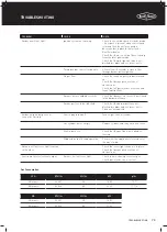


GAS SPECIFICATIONS AND MOBILE RESTRAINT
Turn down adjustment
•
When converting to natural gas the turndown setting will
need to be adjusted to give a satisfactory flame on low
setting on each burner.
•
Remove knob from valve shafts. For ignition valve the
low flame adjustment screw is located on the lower right
hand corner of the front of the valve body
Of
•
Fully insert and rotate a flat bladed screwdriver to adjust
turndown.
•
For non-ignition valves the screw is located inside the
knob spindle. Use a 2.5mm wide flat blade screwdriver
full inserted and make a 3/4 turn counter clockwise.
•
After leak testing light one burner and set to high.
•
One burner at a time turn the valve shaft to lowest
setting observe the flame to ensure a small steady
flame in achieved.
•
Repeat for the other burners.
•
Turn off burners and replace control knobs, ensuring the
knob is in the correct orientation when valve is in “OFF”
position.
Secure all joints and leak test
Never use a naked flame to check for gas leaks. The gas
leak testing procedure should be conducted every time a gas
cylinder is refilled and reconnected to the appliance, or after
any new gas connection is made.
In a small container, mix up a solution of water and
detergent or soap. Mix the solution well.
For LPG/propane make sure that the gas supply valve on the
gas cylinder is turned on. For Natural Gas make sure that
the gas shutoff valve is on.
Make sure that the gas control valves on the appliance are all
turned off.
Using a brush or spray bottle apply the solution to the gas
line and each joint in the gas line.
Bubbling of the solution will indicate that there is a leak
present. Re-tighten or re-seal any joints that are leaking.
If a leak persists contact your distributor or the manufacturer
for assistance.
Check proper burner operation
Following operating instructions, light each burner and
check for a clear blue flame with just a tip of yellow. Excess
yellow tipping can be adjusted using the burner adjustment
screw on the side of the burner. Turn the screw in an anti-
clockwise rotation to reduce the yellow.
Yellow
tipping
Yellow
tipping
Right Wrong
Light
blue
Light
blue
Dark
blue
Dark
blue
65
INSTALLATION WARNINGS
Summary of Contents for 7000 Series
Page 5: ...5 BMF7645SA PRODUCT DIMENSIONS DIMENSIONS 1602 708 1284 ...
Page 7: ...7 BMF7655SA PRODUCT DIMENSIONS DIMENSIONS 1758 708 1284 ...
Page 9: ...9 BMG7642SA PRODUCT DIMENSIONS DIMENSIONS 1602 685 1284 ...
Page 11: ...11 BMG7652SA PRODUCT DIMENSIONS DIMENSIONS 1758 685 1284 ...
Page 15: ...15 ASSEMBLING THE BARBECUE 4 18 19 3 ...
Page 16: ...16 19 15 ASSEMBLING THE BARBECUE 5 6 11 BMF7645SA BMF7655SA ASSEMBLY ...
Page 17: ...17 ASSEMBLING THE BARBECUE 7 8 11 ...
Page 18: ...18 ASSEMBLING THE BARBECUE 17 9 10 BMF7645SA BMF7655SA ASSEMBLY ...
Page 19: ...19 ASSEMBLING THE BARBECUE 11 12 13 16 ...
Page 20: ...20 ASSEMBLING THE BARBECUE 11 13 14 23 BMF7645SA BMF7655SA ASSEMBLY ...
Page 21: ...21 ASSEMBLING THE BARBECUE 15 16 20 22 21 ...
Page 26: ...26 ASSEMBLING THE BARBECUE 25 26 BMF7645SA BMF7655SA ASSEMBLY ...
Page 27: ...27 ASSEMBLING THE BARBECUE 27 28 6 7 ...
Page 28: ...28 ASSEMBLING THE BARBECUE 29 30 BMF7645SA BMF7655SA ASSEMBLY ...
Page 31: ...31 ASSEMBLING THE BARBECUE 35 36 1 Locate the warming rack Sliding locked Sliding unlocked ...
Page 32: ...32 ASSEMBLING THE BARBECUE 10 37 38 9 BMF7645SA BMF7655SA ASSEMBLY ...
Page 33: ...33 ASSEMBLING THE BARBECUE 39 40 8 Spanner 19mm Spanner 22mm ...
Page 39: ...39 ASSEMBLING THE BARBECUE 5 Assemble the back trolley panels with M6 head screws x7 11 11 ...
Page 40: ...40 ASSEMBLING THE BARBECUE 6 7 13 13 BMG7642SA BMG7652SA ASSEMBLY ...
Page 41: ...41 ASSEMBLING THE BARBECUE 17 16 8 9 Assemble the trolley top panel with M6 head screws x8 ...
Page 43: ...43 ASSEMBLING THE BARBECUE 14 12 13 ...
Page 44: ...44 ASSEMBLING THE BARBECUE 14 15 BMG7642SA BMG7652SA ASSEMBLY ...
Page 46: ...46 ASSEMBLING THE BARBECUE 18 19 BMG7642SA BMG7652SA ASSEMBLY ...
Page 47: ...47 ASSEMBLING THE BARBECUE 4 20 21 ...
Page 49: ...49 ASSEMBLING THE BARBECUE 10 24 25 ...
Page 51: ...51 ASSEMBLING THE BARBECUE 28 29 Push down ON to brake Push down OFF to move ...
Page 74: ...74 NOTES NOTES NOTES ...