


Australia only (applies to all gas types) : Where a mobile
appliance is to be connected to a fixed gas supply via a
flexible hose connection, a retaining tether of adequate
strength shall be fixed to the appliance and be suitable to be
fixed to the wall within 50mm of each connection point. The
length of the tether shall not exceed 80% of the length of the
hose assembly. In this way, if the barbecue is accidentally
moved, the chain stops the barbecue from stretching the
hose. The barbecue appliance must be isolated from the
gas supply piping system by closing its manual shutoff valve
during any pressure testing of the gas supply piping system
The barbecue appliance must be isolated from the gas
supply piping system by closing its manual shutoff valve
during any pressure testing of the gas supply piping system.
Converting the unit to natural gas
NOTE: Refer to page 53-58 for natural gas installation
1.
Turn off the gas supply valve on the gas cylinder. Ensure
that all gas controls on the BBQ are in the OFF position.
2.
Disconnect the hose and regulator from the gas cylinder
and disconnect the gas hose from the barbecue gas inlet
using a 19mm open-ended spanner/wrench.
3.
Open hood and remove all cooking plates, grills and
vaporisers from the BBQ.
4.
Remove the ‘R’ shaped locking clips that hold each
burner in place and remove all burners from barbecue.
This needs to be done at the on the front firewall of the
BBQ.
5.
The gas injector (also known as jets or nozzles) for each
burner are located within deep pockets at the on the
front firewall of the BBQ.
6.
Remove each gas injector from the end of each jet
holder using a 6mm socket spanner/wrench, turning
gently in a counter clockwise direction. Be careful not
to block the orifice at the end of valve where the gas
injector is fitted and do not remove any of the thread
sealing compound from the orifice where the injector is
located.
7.
Check the identification mark stamped on Hex Head
of the injector to confirm that it is the correct size (NG:
2.10mm) Screw correct Jet back into place.
8.
When fitting the NG gas injectors to the end of the jet
holder be sure to seat the injector correctly on the
thread before turning it in a clockwise direction until it is
seated firmly in place. Do not over-tighten.
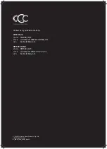
IMPORTANT
Please note: for SL4000 side burners
One the side burner valve, from the inside bend the pilot
ignition tube out the way, unscrew the pilot jet and replace
with the 0.95mm NG jet supplied with the conversion kit.
Once done bend the tube back to the original position if
necessary.
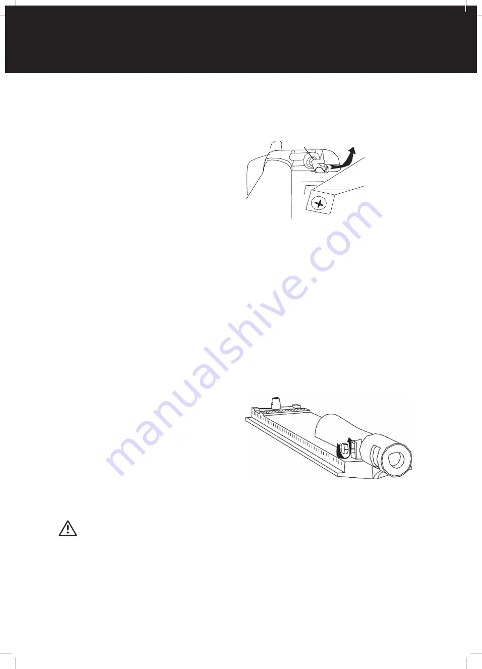
9. Replace all parts into position in the BBQ. Remove the
chute before changing the nozzle and then replace it
when done.
Pilot
Ben
10.
Refit the burners and secure with the locking clips that
hold each burner in position. Replace the vaporisers,
grills and cooking plates. Check the operation of each
burner - on some models it may be necessary to open
the air-mixture screw (located at the burner venturi) a
couple of turns to get the correct flame.
11.
Replace the LPG gas type label with the natural gas
label supplied.
12.
Connect the natural gas hose and regulator (where
applicable) to the gas inlet on the barbecue. Tighten
firmly but do not over tighten. Connect gas regulator
to gas source line. Perform leak testing using same
procedure as for LPG on page 68.
13.
For mobile units attach restraining tether to anchor
point on barbecue, and fasten within 50mm of fixed gas
outlet with suitable fastener. Ensure the length of the
tether does not exceed 80% of the length of the hose to
the fixed gas supply outlet.
INSTALLATION WARNINGS
64
INSTALLATION WARNINGS
Summary of Contents for 7000 Series
Page 5: ...5 BMF7645SA PRODUCT DIMENSIONS DIMENSIONS 1602 708 1284 ...
Page 7: ...7 BMF7655SA PRODUCT DIMENSIONS DIMENSIONS 1758 708 1284 ...
Page 9: ...9 BMG7642SA PRODUCT DIMENSIONS DIMENSIONS 1602 685 1284 ...
Page 11: ...11 BMG7652SA PRODUCT DIMENSIONS DIMENSIONS 1758 685 1284 ...
Page 15: ...15 ASSEMBLING THE BARBECUE 4 18 19 3 ...
Page 16: ...16 19 15 ASSEMBLING THE BARBECUE 5 6 11 BMF7645SA BMF7655SA ASSEMBLY ...
Page 17: ...17 ASSEMBLING THE BARBECUE 7 8 11 ...
Page 18: ...18 ASSEMBLING THE BARBECUE 17 9 10 BMF7645SA BMF7655SA ASSEMBLY ...
Page 19: ...19 ASSEMBLING THE BARBECUE 11 12 13 16 ...
Page 20: ...20 ASSEMBLING THE BARBECUE 11 13 14 23 BMF7645SA BMF7655SA ASSEMBLY ...
Page 21: ...21 ASSEMBLING THE BARBECUE 15 16 20 22 21 ...
Page 26: ...26 ASSEMBLING THE BARBECUE 25 26 BMF7645SA BMF7655SA ASSEMBLY ...
Page 27: ...27 ASSEMBLING THE BARBECUE 27 28 6 7 ...
Page 28: ...28 ASSEMBLING THE BARBECUE 29 30 BMF7645SA BMF7655SA ASSEMBLY ...
Page 31: ...31 ASSEMBLING THE BARBECUE 35 36 1 Locate the warming rack Sliding locked Sliding unlocked ...
Page 32: ...32 ASSEMBLING THE BARBECUE 10 37 38 9 BMF7645SA BMF7655SA ASSEMBLY ...
Page 33: ...33 ASSEMBLING THE BARBECUE 39 40 8 Spanner 19mm Spanner 22mm ...
Page 39: ...39 ASSEMBLING THE BARBECUE 5 Assemble the back trolley panels with M6 head screws x7 11 11 ...
Page 40: ...40 ASSEMBLING THE BARBECUE 6 7 13 13 BMG7642SA BMG7652SA ASSEMBLY ...
Page 41: ...41 ASSEMBLING THE BARBECUE 17 16 8 9 Assemble the trolley top panel with M6 head screws x8 ...
Page 43: ...43 ASSEMBLING THE BARBECUE 14 12 13 ...
Page 44: ...44 ASSEMBLING THE BARBECUE 14 15 BMG7642SA BMG7652SA ASSEMBLY ...
Page 46: ...46 ASSEMBLING THE BARBECUE 18 19 BMG7642SA BMG7652SA ASSEMBLY ...
Page 47: ...47 ASSEMBLING THE BARBECUE 4 20 21 ...
Page 49: ...49 ASSEMBLING THE BARBECUE 10 24 25 ...
Page 51: ...51 ASSEMBLING THE BARBECUE 28 29 Push down ON to brake Push down OFF to move ...
Page 74: ...74 NOTES NOTES NOTES ...